

How to Select the Right Industrial Vibration Sensor in 2026
Bearing faults cause 41–44% of all electric motor failures, according to reliability studies from IEEE and EPRI. Despite that well-known statistic, most engineers still pick sensors by habit — reaching for a 100 mV/g ICP accelerometer regardless of machine speed, mounting constraints, or environment. That habit gets expensive. Unplanned downtime costs manufacturers up to $852M per week globally (GlobeNewswire/Fluke, October 2025), and the wrong sensor won't catch the fault that causes it. The vibration sensor market itself reflects this urgency: it's projected to reach $13.29B by 2033 (Astute Analytica via GlobeNewswire, February 2026). Selection guides exist, but they're locked in vendor PDFs or buried in standards documents most teams don't have time to read. This guide distills the decision into six steps — from machine speed to mounting method — so you can narrow 50-plus sensor models down to two or three real candidates.
Read more: How Do Industrial Sensors Work? The Complete 2026 Guide
TL;DR: Bearing faults account for 41–44% of all motor failures (IEEE/EPRI), making vibration monitoring essential for reliability programs. Choosing the right sensor depends on three factors: machine speed (RPM), measurement point (casing vs. shaft), and environment. Accelerometers suit most general-purpose applications above 600 RPM; velocity sensors handle 10–1,000 Hz mid-range machinery; eddy current proximity probes are required for shaft-relative measurements on critical rotating equipment per API 670.
What Are the Three Core Vibration Sensor Technologies?
MEMS accelerometers show only ±5% deviation from piezoelectric ICP sensors at 0–300 RPM (PMC/NIH, 2024), which means the low-cost wireless option is closer to the gold standard than most reliability engineers realize. But accuracy isn't the only variable. The condition monitoring market sits at $3.29B growing at 7.62% CAGR (Mordor Intelligence, 2025), and sensor choice drives whether that investment pays off.
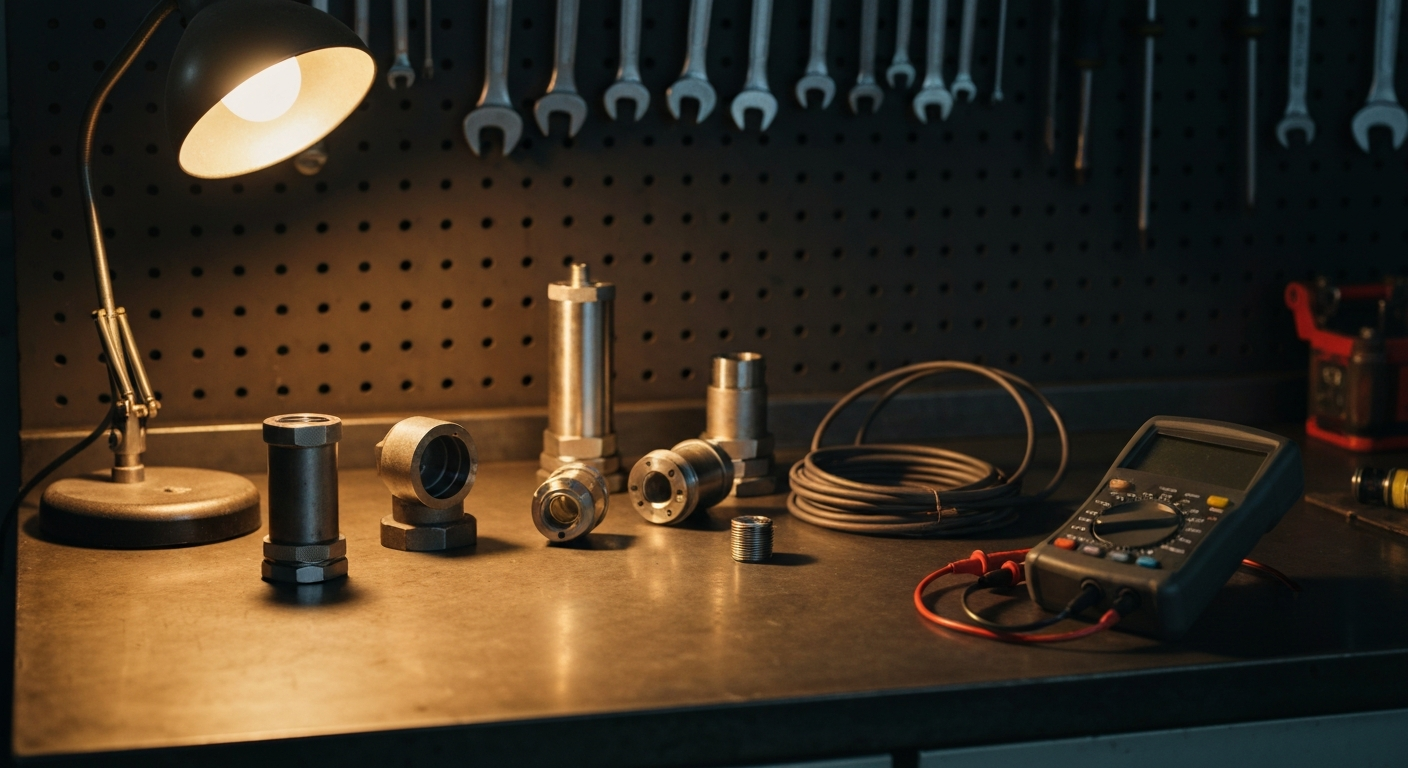
Three core technologies cover 95% of industrial vibration applications. Each measures a different physical quantity, operates across a different frequency band, and fits a different machine type.
Piezoelectric ICP/IEPE accelerometers are the industry workhorse. They measure acceleration in units of g, operate from 0.5 Hz to 20 kHz, and need a constant-current power source — typically 2–20 mA at 18–30 VDC — built into the signal conditioner or data acquisition system. Sensitivity runs from 10 mV/g for high-frequency applications to 500 mV/g for slow-speed machinery.
Velocity sensors (electromechanical or piezoelectric with built-in integration) output velocity in mm/s. They cover 10 Hz to 1,000 Hz — the sweet spot for ISO 10816/ISO 20816 compliance measurements. They're self-generating, so many require no external power, which simplifies wiring in retrofit installations.
Eddy current proximity probes are non-contact displacement sensors. They measure shaft motion relative to the bearing housing, not casing vibration. That distinction matters on journal bearing machines where the shaft can orbit significantly inside the clearance without the casing moving much at all.
MEMS sensors are now accurate enough for most monitoring tasks. The real gap isn't accuracy — it's the low-frequency response below 1 Hz and the sampling rate ceiling around 5 kHz. That ceiling is fine for bearing defect frequencies on most sub-3,600 RPM machinery but won't catch gear mesh harmonics above 5 kHz on high-speed gearboxes. Choose MEMS for balance-of-plant and cost-sensitive IIoT nodes; choose ICP/IEPE for critical machinery or anything above 3,600 RPM.
Read more: How Do Industrial Sensors Work? The Complete 2026 Guide
| Sensor Type | Measures | Frequency Range | Best For | Price Range |
|---|---|---|---|---|
| ICP/IEPE Accelerometer | Acceleration (g) | 0.5 Hz – 20 kHz | General-purpose rotating machinery | $200–$1,500 |
| Velocity Sensor | Velocity (mm/s) | 10 Hz – 1,000 Hz | Mid-range machinery, ISO 10816 compliance | $150–$800 |
| Eddy Current Proximity Probe | Displacement (µm) | DC – 10 kHz | Critical machinery shafts, API 670 compliance | $400–$2,000 |
| MEMS Accelerometer | Acceleration (g) | 0.1 Hz – 5 kHz | Wireless IIoT nodes, cost-sensitive monitoring | $15–$200 |
 Three core technologies cover 95% of industrial vibration applications — each measures a different physical quantity across a different frequency band
Citation Capsule: MEMS accelerometers deviate only ±5% from piezoelectric ICP sensors at low rotational speeds (0–300 RPM), according to a 2024 peer-reviewed study published in PMC/NIH. For general balance-of-plant monitoring, this accuracy is sufficient. The real performance gap is at high frequencies above 5 kHz, where MEMS devices reach their sampling ceiling and ICP accelerometers remain the correct choice.
How Does Machine Speed (RPM) Determine Your Sensor Choice?
Machine RPM is the single most important variable in sensor selection. Below 600 RPM, standard 100 mV/g accelerometers lose sensitivity to the low-amplitude, low-frequency vibration signatures that indicate developing faults. Above 3,600 RPM, high-frequency gear mesh harmonics and blade pass events require extended frequency response well beyond the 10 kHz ceiling of standard sensors.
The physics behind this is straightforward. Bearing defect frequencies — inner race (BPFI), outer race (BPFO), ball spin, and cage frequencies — all scale linearly with shaft RPM. On a motor running at 1,800 RPM with a 6-ball bearing, BPFO typically falls around 50–90 Hz. The same bearing at 600 RPM drops those frequencies to 17–30 Hz, where standard sensors start to struggle.
So what does that mean practically? At 600 RPM, you want 500 mV/g sensitivity — or a proximity probe — to resolve weak low-frequency signals. At 1,800–3,600 RPM, a 100 mV/g ICP sensor covers the job. Above 3,600 RPM, drop to 10 mV/g and confirm the sensor's high-frequency response extends past 20 kHz.
ISO 10816 defines vibration severity zones (A through D) for different machine classes. Velocity sensors are often specified directly for ISO 10816 compliance measurements on mid-range machinery, because the standard expresses limits in mm/s RMS — the native output unit of a velocity sensor.
When we instrumented a 1,200 RPM induced draft fan with a 100 mV/g ICP accelerometer, we detected inner race spalling at BPFI = 87.3 Hz three weeks before the bearing seized. At that speed, the 100 mV/g sensor was borderline — a 500 mV/g unit would have shown the fault signature earlier and more cleanly.
| Machine Speed | Recommended Sensitivity | Frequency Coverage | Typical Applications |
|---|---|---|---|
| < 600 RPM | 500 mV/g or proximity probe | 0.5 Hz – 2 kHz | Slow-speed fans, paper mills, wind turbines |
| 600–1,800 RPM | 100 mV/g | 2 Hz – 20 kHz | Pumps, motors, gearboxes |
| 1,800–3,600 RPM | 100 mV/g | 10 Hz – 20 kHz | Compressors, motors, fans |
| > 3,600 RPM | 10 mV/g | 20 Hz – 50 kHz | High-speed spindles, turbines |
Citation Capsule: Bearing defect frequencies scale directly with shaft rotational speed. On machinery below 600 RPM, standard 100 mV/g accelerometers lose the signal resolution needed to detect early-stage faults. ISO 10816 velocity measurements remain valid across the 10–1,000 Hz mid-range, but machines below 600 RPM require either high-sensitivity (500 mV/g) accelerometers or shaft-relative proximity probes for reliable fault detection.
When Should You Use a Proximity Probe Instead of an Accelerometer?
API 670 mandates eddy current proximity probes for radial and axial shaft vibration monitoring on critical rotating equipment — steam turbines, gas compressors, large centrifugal pumps. The standard is the governing specification for oil & gas, power generation, and petrochemical critical machinery, and it exists because accelerometers simply can't do the job that proximity probes do on these machines.
Here's why. Journal bearing machines allow significant shaft orbit inside the bearing clearance. A shaft can be dangerously close to wipe the bearing while the casing vibration remains low. Proximity probes measure shaft position directly, in micrometers, relative to the probe tip. You can plot shaft centerline position and orbit plots — diagnostics that casing-mounted accelerometers cannot provide.
When should you stay with an accelerometer? On rolling element bearing machines, where the fault energy transmits to the casing well enough for casing-mounted sensors. On machines below API 670 criticality tiers. And anywhere shaft access is impractical.
Proximity probes require careful installation. Gap voltage — typically -10 VDC at the standard 1.0 mm gap — must be set during installation and verified after any maintenance that affects radial clearance. Driver electronics (proximitor modules) are required and add to system cost. On a full API 670 turbine train, probe pairs, drivers, and cabling can add $8,000–$25,000 per measurement plane.
 API 670 mandates proximity probes for shaft vibration on critical rotating equipment — accelerometers simply can't measure shaft orbit inside bearing clearance
Citation Capsule: API 670, the industry standard for machinery protection systems, requires eddy current proximity probes for radial shaft vibration on critical rotating equipment including steam turbines, gas compressors, and large pumps. The standard specifies probe, driver, and system accuracy requirements and is mandatory for most oil & gas and power generation facilities. Accelerometers cannot substitute for proximity probes on journal bearing machinery covered by API 670.
How Do You Evaluate Wired vs. Wireless Vibration Sensors?
Wireless vibration sensors now meet requirements for 40–50% of industrial monitoring points (Crystal Instruments, 2025), but wireless electrical noise runs 1–2 orders of magnitude higher than wired IEPE sensors from the same source. That gap matters less than it used to, but it still determines where wireless belongs in your monitoring architecture.
WirelessHART is the dominant protocol for process plant integration, connecting to existing DCS infrastructure through gateways. Bluetooth Low Energy (BLE) suits IIoT edge nodes with local processing. Proprietary protocols — from vendors like SKF, Emerson, and Fluke — offer tighter integration with their own condition monitoring platforms but lock you into a single ecosystem.
The real constraint with wireless isn't accuracy. It's sampling rate and battery life. A wireless sensor sampling continuously at 10 kHz will drain a standard AA battery in days. Most wireless sensor nodes solve this by sampling periodically — every 5–30 minutes — which is adequate for trend monitoring but misses transient events. For critical machinery requiring continuous monitoring, wired IEPE remains the correct answer.
The sampling rate constraint is the deciding factor, not accuracy. MEMS wireless sensors now achieve ±5% accuracy versus piezoelectric sensors in the relevant frequency range. The architecture question is whether your machinery can tolerate periodic sampling — 15-minute intervals catch slow-developing bearing degradation reliably, but won't capture a sudden imbalance event or a transient fault on a variable-speed drive cycling rapidly through its speed range.
Hard-to-reach locations — rooftop fans, remote pumps, balance-of-plant equipment on large sites — are the natural fit for wireless. Continuous monitoring on critical assets belongs on wired infrastructure.
Citation Capsule: Wireless vibration sensors are now suitable for approximately 40–50% of industrial monitoring points, according to Crystal Instruments (2025). However, wireless signal noise runs 1–2 orders of magnitude above wired IEPE sensors. The practical constraint isn't noise or accuracy — it's the sampling rate and battery trade-off that makes wireless unsuitable for continuous monitoring on critical rotating machinery.
What Environmental Factors Eliminate Sensor Options?
Temperature extremes, hazardous atmospheres (ATEX Zone 1/2, NEC Division 1/2), moisture, and chemical exposure narrow your sensor choice before you evaluate any performance specifications. Environmental factors aren't secondary concerns — they're hard constraints that eliminate entire product categories.
Standard ICP/IEPE accelerometers operate from -50°C to +120°C. That covers the majority of plant environments, including outdoor installations in cold climates and equipment near hot processes. When you're measuring near furnaces, kilns, or exhaust systems above 120°C, standard sensors fail. Charge-mode piezoelectric accelerometers — which don't have internal electronics — can operate to +700°C. They require external charge amplifiers, but that trade-off is often the only viable option.
Hazardous area classification is non-negotiable. ATEX Zone 1 and NEC Class I Division 1 environments require intrinsically safe (IS) or explosion-proof certified sensors. Non-certified sensors in classified areas aren't just a compliance problem — they're a safety hazard. Always confirm certification before ordering.
IP ratings matter too, especially in food processing, pharmaceutical, and outdoor installations where washdown or weather exposure is routine. IP67 (dust-tight, temporary immersion) is the minimum for washdown environments; IP68 suits continuous submersion.
Variable frequency drives (VFDs) generate significant EMI. Sensors installed near VFDs need shielded cable — typically twisted-pair with 360° shield termination at the conditioner end — to avoid injecting noise that masks real vibration signals.
 Environmental factors aren't secondary concerns — ATEX classification and temperature extremes eliminate entire sensor categories before you evaluate performance
| Environment | Required Specification |
|---|---|
| > 120°C surface temperature | Charge-mode PE accelerometer (rated to +700°C) |
| ATEX Zone 1 / NEC Div 1 | Intrinsically safe (IS) certified sensor |
| ATEX Zone 2 / NEC Div 2 | IS or non-incendive (NI) certification |
| Washdown / outdoor | IP67 minimum; IP68 for submersion |
| Near VFDs / high EMI | Low-impedance IEPE + shielded twisted-pair cable |
| Chemical splash / corrosion | Titanium or SS housing; chemically resistant cable jacket |
Citation Capsule: Standard ICP/IEPE accelerometers operate between -50°C and +120°C. Applications above that threshold — furnaces, kilns, exhaust stacks — require charge-mode piezoelectric sensors rated to +700°C with separate charge amplifiers. In classified hazardous areas (ATEX Zone 1, NEC Class I Division 1), only intrinsically safe or explosion-proof certified sensors are permissible. Environmental specification must be confirmed before evaluating performance characteristics.
How Does Mounting Method Impact Measurement Accuracy?
Mounting method can reduce your usable frequency range by 80% or more. A stud-mounted accelerometer delivers the sensor's full rated bandwidth. A magnetic mount cuts usable bandwidth by 80%. A handheld probe loses 95% of the high-frequency response. The numbers are stark: stud mount gets you to 10 kHz; adhesive epoxy to 5 kHz; magnetic mount to 2 kHz; handheld probe to 500 Hz (PCB Piezotronics vibration monitoring application note).
Why such a large difference? Resonance. A magnetic or adhesive mount adds mechanical compliance between the accelerometer base and the machine surface. That compliance creates a resonant system with the sensor mass. As vibration frequency approaches that resonant frequency, the measurement amplifies, then drops off — the sensor is no longer measuring machine vibration, it's measuring the mount's resonance.
Stud mounting requires surface prep: the mounting surface must be flat within 0.025 mm and smooth (Ra ≤ 0.8 µm). The mounting stud torque spec matters — typically 2.5–3.5 N·m for a 10-32 stud. Under-torqued studs allow micro-motion that degrades high-frequency response almost as badly as a magnetic mount.
Adhesive mounting (cyanoacrylate or epoxy) delivers solid high-frequency performance if the adhesive fully cures and the surface is clean. Cyanoacrylate cures in minutes but has lower temperature resistance. Epoxy takes longer but handles higher temperatures.
Magnetic mounts are acceptable for route-based periodic measurements on sub-1,800 RPM machinery where bearing defect frequencies fall below 1,500 Hz. Don't use magnetics on high-speed machinery where gear mesh or blade-pass frequencies matter.
On that same induced draft fan installation at 1,200 RPM, using a magnetic mount instead of a stud cut our usable bandwidth from 10 kHz to 2 kHz. That was enough for bearing defect detection — BPFI at 87.3 Hz sat well below the 2 kHz ceiling. But it would have missed gear mesh frequencies above 2 kHz had we been monitoring the gearbox on the same route. Know your target fault frequencies before you accept a mounting compromise.
Citation Capsule: Accelerometer mounting method determines usable bandwidth more than sensor specification alone. According to PCB Piezotronics Technical Note TN-17, stud mounting provides a 10 kHz upper limit; adhesive epoxy 5 kHz; magnetic mount 2 kHz; and handheld probe 500 Hz. Using a magnetic mount on machinery where gear mesh or blade-pass frequencies exceed 2 kHz will produce measurements that appear valid but miss the fault modes that matter most.
Frequently Asked Questions
What sensitivity (mV/g) do I need for general industrial vibration monitoring?
For most rotating machinery between 600 and 3,600 RPM — motors, pumps, fans, gearboxes — a 100 mV/g ICP accelerometer is the correct starting point. Below 600 RPM, step up to 500 mV/g to maintain signal resolution on low-amplitude fault signatures. Above 3,600 RPM, use 10 mV/g to avoid amplifier saturation on high-g shock events.
What vibration sensor works best for slow-speed machinery below 600 RPM?
Below 600 RPM, you have two valid options: a high-sensitivity 500 mV/g ICP accelerometer or an eddy current proximity probe. MEMS accelerometers rated to 0.1 Hz also work for this range (PMC/NIH, 2024). For paper mill rolls, wind turbine main bearings, and other slow-speed applications, proximity probes typically deliver more reliable data on shaft displacement.
How do I connect a vibration sensor to my PLC or DCS?
Standard ICP/IEPE accelerometers require a signal conditioner between the sensor and your control system. Most PLC and DCS inputs accept 4–20 mA signals — use a vibration transmitter that converts the raw accelerometer signal to a 4–20 mA loop output proportional to velocity (mm/s RMS) or acceleration (g RMS).
Do I need triaxial or single-axis vibration measurement?
Single-axis sensors cover most route-based and permanently installed monitoring applications. Triaxial sensors reduce installation time and cost when you need simultaneous X, Y, Z data — for example, during modal analysis or when diagnosing misalignment, where axial vibration patterns matter. Most ISO 10816 measurements are radial; add axial only when thrust or misalignment faults are the concern.
What is the difference between ICP/IEPE and charge-mode accelerometers?
ICP (Integrated Circuit Piezoelectric) and IEPE (Integrated Electronics Piezo-Electric) sensors have built-in amplifiers powered by a constant-current source — typically 2–20 mA at 18–30 VDC. Charge-mode sensors have no internal electronics and require an external charge amplifier. The trade-off: ICP/IEPE is easier to wire and cable, but tops out around 120°C. Charge-mode handles temperatures to +700°C for high-heat applications.
Conclusion
The six-step framework here — machine speed, measurement point, environment, protocol, mounting, budget — reliably narrows any selection from 50-plus catalog entries to two or three real candidates. Here's how the priorities stack:
- Start with RPM. Speed defines sensitivity, frequency range, and whether you're in proximity probe territory.
- Confirm the measurement point. Casing acceleration (accelerometer or velocity) versus shaft displacement (proximity probe) is a binary decision driven by bearing type and API criticality tier.
- Lock the environment first. Temperature, hazardous area classification, and IP rating eliminate non-compliant sensors before you compare specs.
- Choose mounting method. Accept the bandwidth trade-off consciously. A magnetic mount is fine at 1,200 RPM; it's wrong at 3,600 RPM.
- Then evaluate wired vs. wireless. Wireless is viable for 40–50% of points (Crystal Instruments, 2025). Use it where it genuinely reduces cost or improves coverage.
- Apply budget last. Predictive maintenance yields up to 10x ROI and reduces maintenance costs by 30–40% (Advanced Technology Services, 2025). The sensor cost is rarely the limiting factor in a sound reliability program.
The right sensor, correctly installed, gives you the signal. Everything else — alarm limits, trending, fault classification — depends on getting that first step right.
Read more: How Do Industrial Sensors Work? The Complete 2026 Guide Read more: Pressure Sensor Types Compared: Gauge, Absolute, and Differential
Tags