

Debouncing 101: Stop Proximity Sensor Chattering in PLC Logic
The part counter read 1103. The production run was exactly 1000 parts. Twelve phantom detections every shift - counts that corrupt OEE numbers, fire incorrect downstream logic, and vanish completely when maintenance arrives to investigate. The usual response is to increase the PLC input filter from 2 ms to 20 ms and wait. It works for a week. Then the counts start drifting again.
Most troubleshooting guides call this "contact bounce" and recommend a longer debounce timer. That diagnosis is wrong, and so is the cure - but it's an understandable mistake, because proximity sensors behave nothing like the pushbuttons and limit switches that debouncing theory was originally designed for.
Proximity sensors have solid-state transistor outputs. Nothing physically moves when the output switches. There is no contact to bounce. IEC 60947-5-2 defines a "false pulse" as an undesired output change lasting more than 2 ms - and false pulses on a solid-state proximity output have three specific root causes: target dwell at the sensing boundary, machine vibration that exceeds the sensor's hysteresis band, and EMI coupling from VFDs, welders, or large contactors. A debounce timer doesn't touch any of them. This guide shows you what actually causes proximity sensor chatter and how to eliminate it at the source.
For a broader view of how industrial sensors work across measurement domains, the complete guide covers the full landscape.
TL;DR: Proximity sensor chatter is not mechanical contact bounce - solid-state transistor outputs don't physically bounce. The three real causes are target dwell at the switching boundary, vibration amplitude exceeding the sensor's hysteresis band, and EMI from VFDs or welders. IEC 60947-5-2 caps hysteresis at 20% of rated sensing distance. Fix mounting and hysteresis first. Use a PLC debounce timer (2-3 ms for EMI, 10-50 ms for boundary or vibration chatter) only as a backstop, not a solution.
What Is Proximity Sensor Chatter, and Why Does It Happen?
Chatter is rapid, unintended toggling of the sensor output. IEC 60947-5-2 defines a false pulse as any undesired output change lasting more than 2 ms, and industrial automation guidance identifies three root causes: target dwell at the sensing boundary, machine vibration whose peak amplitude exceeds the sensor's hysteresis band, and EMI coupling from nearby high-power equipment (NotebookLM research). Which of the three is active determines which fix works.
 Conveyor vibration is a prime chatter source: when peak amplitude exceeds the sensor's hysteresis band, the output toggles on every pass.
The sensing boundary is the thin zone where the sensor's oscillator field crosses the switching threshold. Most sensors spend the vast majority of their service life with the target either well inside the field (output firmly ON) or well outside it (output firmly OFF). Chatter only happens when the target lingers right at the edge. A slow-moving target, a part with loose mechanical fixturing, or a worn conveyor chain can all put the target into that unstable zone on every machine cycle.
Machine vibration is a subtler mechanism. Every inductive and capacitive sensor has a hysteresis band - a deliberate gap between the switch-on point and the switch-off point. Vibration whose amplitude is smaller than the hysteresis band produces no problem: the output stays stable even as the target oscillates slightly. But when vibration amplitude exceeds the hysteresis band, the target crosses both the switch-on and switch-off thresholds with every vibration cycle. That's not an occasional glitch - it's guaranteed chatter at the vibration frequency (NotebookLM research). A machine with a 25 Hz resonance and a target mounted too far from the sensor face produces exactly 25 false pulses per second.
EMI from variable-frequency drives, welding equipment, and large motor starters is the third cause. It couples electrically into the sensor signal cable and appears at the PLC input as short-duration noise spikes. Unlike the other two causes, EMI-driven chatter doesn't track the machine cycle - it tracks the interference source. A count spike that happens every time the VFD ramps to full speed isn't random.
What do all three causes have in common? None of them involve mechanical contact bounce. And that distinction changes everything about how you fix it.
Is Sensor Chatter the Same as Contact Bounce?
Mechanical contact bounce and proximity sensor chatter are completely different phenomena. Contact bounce is a physical event: relay and limit switch contacts vibrate at the moment of closure, producing microsecond-scale multiple closures before settling. Solid-state proximity sensors have no moving contacts - their outputs are transistors, and transistors don't bounce (NotebookLM research). Misidentifying the cause is the single most common reason a "fixed" chatter problem returns within a week.
This distinction is worth slowing down on. Pushbutton debounce filters - the ones built into most PLC input modules by default, and the ones described in dozens of ladder logic tutorials - were designed for mechanical contacts bouncing at 50 to 500 microsecond intervals. A standard 5 ms filter is more than adequate for pushbutton bounce. Applied to a proximity sensor with vibration-driven chatter at 25 Hz, that same 5 ms filter might suppress the shortest spikes but won't stabilize the output if the target is physically crossing the hysteresis boundary twenty-five times per second. The timer only masks the symptom while the root cause keeps producing false pulses.
Here's the field consequence. A maintenance tech increases the PLC input filter from 5 ms to 100 ms and declares victory. For the rest of that shift, it works. Three days later, a different product runs on the same conveyor - slightly different target mass, slightly different machine resonance - and the counts drift again. Now the only remaining fix is a filter long enough to introduce real detection delay, and that delay starts causing missed parts on faster products. The "fix" has made the situation worse.
The durable solution starts by asking which of the three root causes is present, then eliminating it at the source. Software filtering is the final step, not the first.
Citation capsule: Solid-state proximity sensors use transistor outputs with no moving parts and cannot produce mechanical contact bounce. IEC 60947-5-2 defines a false pulse as an undesired output change lasting more than 2 ms. The root causes of proximity sensor chatter are target dwell at the switching boundary, vibration amplitude exceeding the hysteresis band, and EMI coupling from high-power equipment. Source: IEC 60947-5-2; NotebookLM research.
Before You Start: What to Check First
Before adjusting any PLC filter or writing debounce logic, a five-point pre-diagnosis checklist saves hours of trial and error. IEC 60947-5-2 specifies that a sensor's "time delay before availability" - the startup latency before the output is valid - must not exceed 300 ms (IEC 60947-5-2). Give the sensor a power cycle and watch for false pulses during that window before assuming the problem is steady-state chatter.
Work through these checks in order:
1. Identify the sensor technology. Inductive, capacitive, and photoelectric sensors have different hysteresis specs and different EMI susceptibilities. The fix differs by type. If you're unsure, the datasheet will say. Look for "inductive," "capacitive," or "diffuse/retroreflective/through-beam" in the product description.
2. Find the hysteresis specification. The datasheet lists hysteresis as a percentage of rated sensing distance (Sr). General-purpose inductive sensors typically run 10% of Sr; precision flat-pack models around 5%; harsh-environment models 12-15% (NotebookLM research). Compare this to the vibration amplitude you can measure or estimate at the target face.
3. Verify the actual mounting gap. Measure the gap between the sensor face and the target using a feeler gauge or digital caliper. It should be no more than 80% of the sensor's assured operating distance (Sa). Sensors mounted at the very edge of their rated range have almost no margin for vibration amplitude or thermal drift before the target enters the boundary zone.
4. Inspect the cable run. Is the sensor cable routed parallel to VFD output cables, motor power leads, or welding return conductors? Long parallel cable runs between sensor cables and power cables are the primary EMI coupling path. Note the total cable length - longer cables have higher antenna gain for high-frequency transients.
5. Confirm PLC input module filter capability and scan time. Check the module manual for available filter settings. Record the PLC scan time - a software debounce timer shorter than the scan time cannot observe the pulse and therefore cannot filter it. Both numbers constrain what's achievable in software.
Once you've answered these five questions, the correct fix usually becomes apparent before you've changed anything.
How Does Hysteresis Stop Chatter at the Source?
Hysteresis is the deliberate gap between the switch-on and switch-off points in a proximity sensor's output. IEC 60947-5-2 caps it at 20% of the sensor's rated sensing distance (Sr) and requires it to be non-zero - a zero-hysteresis sensor would oscillate continuously at the switching boundary (IEC 60947-5-2). General-purpose sensors run about 10% of Sr; precision flat-pack models around 5%; harsh-environment sensors 12-15% (NotebookLM research). When hysteresis exceeds the peak vibration amplitude at the target face, the target cannot cross both thresholds in a single vibration cycle - and chatter stops.
 On rotating equipment, hysteresis larger than the peak vibration amplitude is what keeps the output from oscillating at the switch point.
The logic is straightforward. Say a sensor has a 10 mm rated operating distance and 10% hysteresis. The switch-on point might be at 8 mm, the switch-off point at 9 mm - a 1 mm hysteresis band. If the machine vibrates with 0.3 mm amplitude at the target face, the target oscillates within a 0.6 mm window. Since 0.6 mm is less than 1 mm, the target never crosses both thresholds in a single vibration cycle. Output stays stable.
Now change one variable. Same sensor, same mounting, but machine resonance shifts and vibration amplitude grows to 0.7 mm - a 1.4 mm window. That window exceeds the 1 mm hysteresis band. Guaranteed chatter, every vibration cycle, until something changes (NotebookLM research).
The fix has two paths. First, reduce the vibration amplitude at the sensor bracket. Stiffer mounting, vibration-damping hardware, or addressing the machine resonance that drives the amplitude. Second, choose a sensor with a wider hysteresis band. Harsh-environment proximity sensors with 12-15% hysteresis exist precisely for high-vibration applications.
Mounting distance matters too. A sensor installed at 50% of its rated range operates near the center of its sensing field, where the hysteresis band is widest. A sensor at 90% of rated range is near the boundary where the band is narrowest. Moving the sensor 1-2 mm closer to the target is often the cheapest and fastest fix for boundary-dwell chatter. For a comparison of sensor types, switching frequency limits, and selection criteria by material, see the guide to choosing the right proximity sensor by technology and application.
Citation capsule: IEC 60947-5-2 caps proximity sensor hysteresis at 20% of rated sensing distance (Sr) and requires it to be non-zero. Typical values by sensor class: precision flat-pack 5%, general-purpose 10%, harsh-environment 12-15% of Sr (NotebookLM research). Vibration-driven chatter is guaranteed when the vibration amplitude at the target face exceeds the hysteresis band width, because the target crosses both switch-on and switch-off thresholds in every vibration cycle. Source: IEC 60947-5-2; NotebookLM research.
How Do PLC Input Filters Work?
PLC input modules include configurable digital filters that require the signal to remain stable for a set time before registering a state change. For electrical noise and EMI-driven spikes, 2-3 ms of filtering is usually sufficient. Mechanical contacts require 50-100 ms because physical bounce intervals can last that long. Proximity sensor chatter driven by boundary dwell or vibration typically falls between those extremes, needing 10-50 ms (industrial automation guidance; IEC 60947-5-2).
Here's the vendor reality check: most PLC manufacturers don't publish universal default input filter values in public web documentation. Filter time is a parameter you configure in the vendor's programming tool, and it varies by module. Siemens digital input modules reference approximately 3.2 ms in some module documentation - that's a reasonable EMI filter starting point for a proximity sensor signal, but it's not a universal default and it doesn't apply to all Siemens modules. For Rockwell (Studio 5000), Omron (CX-Programmer, Sysmac), or any other platform, open the I/O module properties in your programming environment and read the filter parameter directly. Don't assume a number found in a forum post applies to your hardware.
Does the filter time even matter in your application? Run a quick sanity check: the filter must be shorter than the valid detection window. At 100 parts per minute, each part is present for 600 ms - a 20 ms filter is fine. At 3000 parts per minute, each part is present for only 20 ms. A 20 ms filter means the confirmed output barely latches before the next part arrives. The filter time and machine cycle rate must both fit on the same timeline.
EMC immunity at the sensor level is a separate line of defense. IEC 60947-5-2 in conjunction with the IEC 61000-4 series specifies Electrical Fast Transient (EFT) immunity of +/-2 kV on power lines and +/-1 kV on I/O lines, plus ESD immunity of +/-8 kV air discharge and +/-4 to 6 kV contact discharge (IEC 60947-5-2 / IEC 61000-4). A sensor that meets these specifications will reject most plant-floor EMI on its own. A sensor wired with unshielded cable running adjacent to a VFD output can fail EFT immunity in practice regardless of what the spec sheet says - the cable becomes an antenna. Fix the cable first, then evaluate whether any software filter is still needed.
How Do You Debounce a Proximity Input in Ladder Logic?
The standard TON (timer-on-delay) pattern requires the input signal to stay stable for a defined period before the confirmed output latches. Set the TON preset to the filter time appropriate for the chatter cause: 2-3 ms for EMI, 10-50 ms for boundary or vibration chatter. Every noise spike resets the timer - only a signal that stays continuously active for the full preset duration produces an output (industrial automation guidance).
Here's how the pattern works across three rungs:
Rung 1 - Start the timer when the raw sensor signal goes ON:
The raw proximity input (not yet debounced) starts the TON timer. The timer's Done bit is wired in series as a normally-closed contact so the timer resets automatically once it completes - this keeps the rung clean without a separate reset rung for the ON condition.
Rung 2 - Latch the confirmed output when the timer completes:
The timer's Done bit directly energizes the confirmed output coil. Until the timer runs its full preset, the confirmed output stays OFF even if the raw input is active. This is the "stable for X ms" gate.
Rung 3 - Reset the timer if the signal drops before the preset expires:
A normally-closed contact from the raw input drives a reset (RES) instruction on the timer. If the raw signal goes OFF at any point during the preset period - a noise spike, a brief target crossing - the timer resets to zero and must start over. The confirmed output never fires for a transient.
A critical scan-cycle caveat applies here. If the PLC scan time is 10 ms and the TON preset is 20 ms, the timer needs at least two full scans to complete - that's fine. But if a noise spike lasts only 3 ms and the scan time is 15 ms, the PLC may never observe the spike within a single 15 ms scan window. In that case, the PLC hardware input filter is the right tool, not a software timer. Software debounce works best for chatter events longer than the scan time; hardware filters catch transients shorter than the scan.
There's one more timing interaction to verify. Capacitive proximity sensors in standard housings are limited to roughly 10 Hz typical (IS 13947 / IEC) - a switching period of about 100 ms. A 50 ms TON filter on top of a 10 Hz sensor leaves very little margin for a valid pulse to arrive, be recognized, and latch before the target moves on. Always check sensor switching frequency against filter time and machine cycle time together, not independently. The proximity sensor comparison guide covers switching frequency specs across inductive, capacitive, and photoelectric technologies.
Hardware vs Software Debounce: Which Should You Use?
The right answer is hardware first, then software as a backstop. Hardware fixes - correct mounting distance, a sensor with adequate hysteresis for the vibration environment, and properly shielded cable - eliminate the root cause. A PLC software filter only masks the symptom while adding response delay to every detection event, not just the chattery ones (industrial automation guidance).
The decision splits cleanly by cause:
Chatter correlates with machine vibration? Choose a sensor with a wider hysteresis band for the operating environment, or stiffen the sensor bracket. Harsh-environment proximity sensors with 12-15% hysteresis exist for exactly this reason. Adding a software filter on a vibration-driven input treats the symptom while the root cause continues to stress the sensor and bracket hardware.
Chatter correlates with VFD speed changes or motor starts? Run shielded cable, terminate the shield at one end only (panel end, not sensor end), and route the cable at least 200 mm away from power wiring. An RC filter plus Schmitt trigger on the sensor output provides hardware hysteresis that sharpens noisy signal edges without adding delay to valid detections. Double-ended shield termination creates a ground loop that can induce the very noise you're trying to suppress.
Chatter correlates with a target approaching a specific conveyor position? The sensor is mounted too far from the target. Moving the sensor 1-2 mm closer centers the target in the hysteresis band during that position and eliminates boundary dwell without any logic change.
Software debounce adds delay uniformly - it slows down every detection, not just the noisy ones. On fast-cycling applications, that latency reduces effective throughput. Fix the hardware root cause, then confirm the fix with a short (2-3 ms) software filter as a final backstop against residual transients that occasionally slip through. That's the correct order of operations.
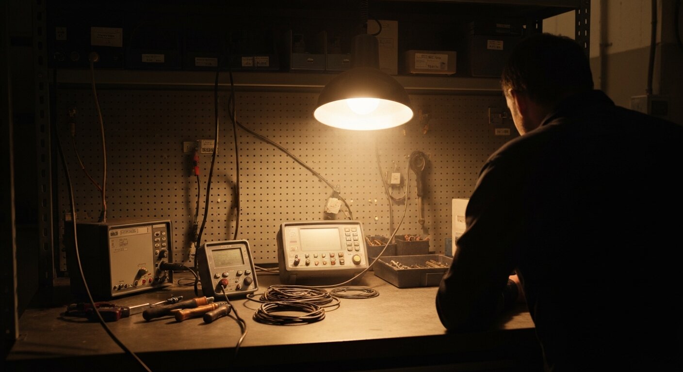
[PERSONAL EXPERIENCE]: The machines most prone to proximity sensor chatter are welding cells and stamping presses. Both have high vibration, high EMI, and targets that dwell at the sensing boundary during tooling transitions. All three root causes can appear simultaneously on the same sensor. The fastest field triage: disconnect the sensor cable at the PLC input card and connect a known-good DC supply directly to that input through a toggle switch. Toggle manually and watch the PLC point. If the point is rock-solid with the external supply, the chatter is in the sensor or cable - not in the PLC logic. If the point still glitches with the external supply connected, suspect the input card or backplane noise.
How Do You Diagnose a Chattering Proximity Input?
If you're not already confident about NPN vs PNP wiring and sinking/sourcing input conventions, verify the wiring first. A type mismatch or a loose connection at the input terminal can produce input glitches that look identical to chatter but have a completely different fix. Correct wiring is the prerequisite before any chatter diagnosis.
 Scope the raw signal wire first: EMI-driven chatter shows up as sub-2 ms spikes that line up with VFD or welder activity.
Step 1 - Capture the chatter pattern with a data logger or scope. Open the PLC online monitor and watch the raw input bit in real time. Note the duration of the glitches. Sub-2 ms spikes point to EMI (per the IEC 60947-5-2 false-pulse definition). Longer, irregular transitions at a fixed frequency point to vibration. Transitions that track a slow-moving target approaching a specific position point to boundary dwell. Without capturing the pattern, every subsequent fix is guesswork.
Step 2 - Correlate chatter events with machine activity. Does it happen when the VFD ramps to full speed? When the weld fires? When a specific servo axis accelerates? Correlation identifies the energy source. If chatter appears random and uncorrelated with any machine event, check cable continuity and connector contact quality first. Intermittent connection resistance mimics EMI chatter and is surprisingly common on connectors in high-vibration environments.
Step 3 - Measure the actual mounting gap. Use a calibrated feeler gauge or digital caliper. Compare the gap to the sensor's rated operating distance. If the gap exceeds 80% of the rated range, the sensor is operating near the boundary zone. Move it closer.
Step 4 - Check cable shielding and routing. Verify the shield is terminated at one end only. Measure the separation between the sensor cable and any VFD output cable along the full run. If any parallel run exceeds 500 mm at less than 200 mm separation, that's the coupling path.
Step 5 - Swap in a known-good sensor. If chatter persists after addressing mounting gap and cable routing, replace the sensor with a unit of the same type from sealed stock. If chatter disappears, the original sensor's internal oscillator has drifted out of spec. Replace it.
The same correlation-first methodology applies to analog noise problems on 4-20 mA current loops. For the analog diagnostic counterpart, see troubleshooting 4-20 mA loop noise.
Frequently Asked Questions
What is the difference between proximity sensor chatter and mechanical contact bounce?
Mechanical contact bounce is physical vibration of relay or limit switch contacts at the moment of closure, producing rapid microsecond-scale closures before the contacts settle. Proximity sensors have solid-state transistor outputs with no moving parts - they cannot mechanically bounce (NotebookLM research).
Proximity sensor chatter comes from target dwell at the sensing boundary, vibration amplitude exceeding the hysteresis band, or EMI coupling from nearby VFDs or welders. The root causes are completely different from contact bounce, which is why pushbutton debounce timers only mask the symptom rather than fixing it.
What hysteresis value should I specify for a proximity sensor?
IEC 60947-5-2 caps hysteresis at 20% of rated sensing distance (Sr) and requires it to be non-zero. Typical values by class: general-purpose inductive runs about 10% of Sr, precision flat-pack around 5%, and harsh-environment models 12-15% (NotebookLM research).
Specify a sensor whose hysteresis band exceeds the expected peak vibration amplitude at the target face. If your machine vibrates with 0.8 mm amplitude at the sensor bracket and the rated distance is 10 mm, you need at least 10% hysteresis (1 mm band) to remain stable. Harsh-environment sensors at 12-15% add further margin.
What PLC input filter time should I use for a proximity sensor?
Match filter time to the chatter cause: 2-3 ms clears electrical noise and EMI, 10-50 ms handles boundary dwell and vibration-driven chatter (industrial automation guidance). Mechanical contacts need 50-100 ms - proximity sensors rarely need that much.
Always verify the specific value in your module manual rather than assuming a generic default. Siemens digital input modules reference approximately 3.2 ms in some module documentation, but Rockwell and Omron values vary by module and must be read from the programming tool directly. Unlike a software timer, a hardware module filter runs in real time, independent of the scan cycle, so even a 3 ms filter stays effective on a slower scan.
How do I tell if EMI is causing my proximity sensor to chatter?
Chatter that correlates with VFD speed changes, welder firing cycles, or large motor starts is almost always EMI. Verify with a scope or data logger on the raw sensor signal wire: look for short spikes under 2 ms coinciding with the interference event (per the IEC 60947-5-2 false-pulse definition).
The hardware fix is shielded cable with single-point shield termination at the panel end, routing the cable at least 200 mm away from VFD output and motor power wiring. After fixing the cable, a 2-3 ms PLC input filter clears most residual EMI-driven spikes (industrial automation guidance).
Should I fix proximity sensor chatter in hardware or software?
Hardware first. Correct mounting distance within 80% of rated range, adequate sensor hysteresis for the vibration environment, and properly shielded cable remove the root cause. A PLC debounce timer adds the same response delay to every detection event - on fast targets that delay causes missed counts, not fewer false ones.
Standard capacitive sensors are already limited to roughly 10 Hz typical in many standard housings (IS 13947 / IEC); stacking a long software filter reduces effective throughput further. Fix the source, then add the minimal filter needed as a backstop against residual transients.
Conclusion
Three things to take away from this guide:
-
Proximity sensor chatter is not contact bounce. Solid-state transistor outputs don't physically bounce. The three real causes are target dwell at the sensing boundary, vibration amplitude exceeding the sensor's hysteresis band, and EMI coupling from VFDs or welders. Identifying which cause is active determines which fix is right - and none of them respond well to a longer debounce timer alone.
-
Hysteresis is the primary hardware defense against chatter. IEC 60947-5-2 caps it at 20% of rated sensing distance. General-purpose sensors run about 10%; harsh-environment models 12-15%. When machine vibration amplitude exceeds the hysteresis band, chatter is guaranteed regardless of any software filter you apply. Fix the mounting distance and sensor selection first.
-
PLC debounce filters are a backstop, not a solution. Use 2-3 ms for EMI, 10-50 ms for boundary or vibration chatter. A software debounce timer must exceed one PLC scan cycle to take effect; a hardware module filter works independently of scan time. Never substitute a longer timer for a hardware fix - it adds detection delay uniformly and leaves the root cause in place.
For context on how proximity sensors fit into the broader industrial measurement landscape, see the complete guide to industrial sensors. For the next logical diagnostic step - troubleshooting noise on analog sensor signals using the same correlation-first approach - see the guide on troubleshooting 4-20 mA loop noise.
Frequently Asked Questions
What is the difference between proximity sensor chatter and mechanical contact bounce?
Mechanical contact bounce is physical vibration of relay or limit switch contacts at closure, producing rapid microsecond-scale closures before settling. Proximity sensors have solid-state transistor outputs with no moving parts - they cannot bounce. Proximity sensor chatter is caused by target dwell at the sensing boundary, vibration amplitude exceeding the hysteresis band, or EMI coupling from nearby VFDs or welders (NotebookLM research).
What hysteresis value should I specify for a proximity sensor?
IEC 60947-5-2 caps hysteresis at 20% of rated sensing distance (Sr) and requires it to be non-zero. In practice, general-purpose sensors run about 10%, precision flat-pack sensors around 5%, and harsh-environment sensors 12-15% of Sr (NotebookLM research). Specify a sensor whose hysteresis band exceeds the peak vibration amplitude at the target face - if it doesn't, vibration-driven chatter is guaranteed on every vibration cycle.
What PLC input filter time should I use for a proximity sensor?
Match filter time to the cause: 2-3 ms clears electrical noise and EMI, 10-50 ms handles boundary dwell and vibration-driven chatter. Always verify in your module manual. Siemens digital input modules reference approximately 3.2 ms in some module documentation, but Rockwell and Omron values vary by module. Never set filter time shorter than the PLC scan cycle - a filter shorter than the scan time cannot take effect (industrial automation guidance).
How do I tell if EMI is causing my proximity sensor to chatter?
Chatter that correlates with VFD speed changes, welder firing cycles, or large motor starts is almost always EMI. Verify with a scope or data logger: look for short spikes under 2 ms (IEC 60947-5-2 false-pulse definition) coinciding with the interference event. The fix is shielded cable with single-point shield termination at the panel end, routed at least 200 mm away from VFD output and motor power wiring (industrial automation guidance).
Should I fix proximity sensor chatter in hardware or software?
Hardware first. Correct mounting distance, adequate sensor hysteresis, and properly shielded cable remove the root cause. A PLC debounce timer adds the same response delay to every detection - on fast targets that matters. Standard capacitive sensors are already limited to roughly 10 Hz typical in many housings (IS 13947 / IEC); stacking a long software filter reduces throughput further. Fix the source, then use the minimal filter needed as a backstop.