

Flow Meter Commissioning Checklist: The Ultimate Walkdown Guide
A useful flow meter commissioning checklist ends with evidence for each acceptance decision. A powered transmitter and a plausible number on the operator screen are only part of the walkdown. The piping, device configuration, receiving system, and intended measurement duty all need checking.
This guide provides a practical record structure for engineers and technicians commissioning an installed meter. Manufacturer instructions supply the technical requirements; the checklist records how they apply. For example, the Promag 10 brief instructions separate installation and wiring checks from commissioning. That separation is worth preserving.
TL;DR: Work from the installed model's manual. Record mechanical readiness, configuration, output-path tests, zero-check conditions, and live-flow results separately. A 4–20 mA loop test does not establish flow accuracy. Close each checklist row with an observed result, acceptance basis, evidence location, and responsible person before requesting handover.
What should the flow meter commissioning checklist capture?
Use a checklist that connects every accepted item to an observation and a requirement. Manufacturer manuals give model-specific instructions; the record below is a proposed way to organize them. Start with the exact meter identity, then keep installation, signal testing, and measurement evidence in separate rows.
| Walkdown gate | Evidence to retain | Suggested hold point |
|---|---|---|
| Identity and authorization | Tag, serial numbers, manual revision, approved work scope | Equipment or authority does not match the task |
| Mechanical installation | Orientation, pipe condition, nearby fittings, manual references | Installation deviation lacks an approved disposition |
| Electrical installation | Wiring checks, supply details, grounding arrangement | Connection or protection remains unresolved |
| Configuration and outputs | Saved settings, channel mapping, test results | Local and receiving-system values disagree |
| Zero and live flow | Process conditions, observations, applicable reference | Test conditions or acceptance basis are missing |
| Handover | Accepted results, open issues, responsible signatures | Outstanding issue has no owner or disposition |
These are proposed project hold points, not a substitute for the site's permit or startup procedure. Agree them before the walkdown. A commissioning technician should not have to negotiate the meaning of “acceptable” while a process operator is waiting to start equipment.
If the meter technology itself remains uncertain, start with the flow meter types comparison. This checklist assumes selection is complete and asks whether the installed system is ready for its assigned duty.
Step 1: Establish identity, scope, and authority
Match the physical meter to the documents before changing settings or operating valves. The Promag 10 instructions reserve installation, connection, commissioning, and maintenance for qualified, authorized specialists. Use that requirement alongside the site's work controls and the instructions for the actual equipment.
Record the sensor and transmitter tags, serial numbers, process service, and relevant manual revisions. Include remote components where fitted. Put the approved datasheet, piping drawing, wiring drawing, configuration record, and applicable calibration documentation within reach of the person performing the work.
Define the boundary of the test. Are you checking the transmitter output, the complete path to the controller, or a measurement against a reference? Write that boundary on the sheet. Also identify who may authorize energization, process admission, output forcing, control bypasses, and return to normal operation.
Hold the work if the equipment identity or authorization is uncertain. This article does not supply a valve-operating sequence, isolation plan, or permission to defeat an interlock.
Use one evidence folder for the tag. Save photographs of the installed arrangement where allowed, references to controlled documents, and the as-found configuration. Avoid a checklist whose supporting files live only on the commissioning engineer's laptop.
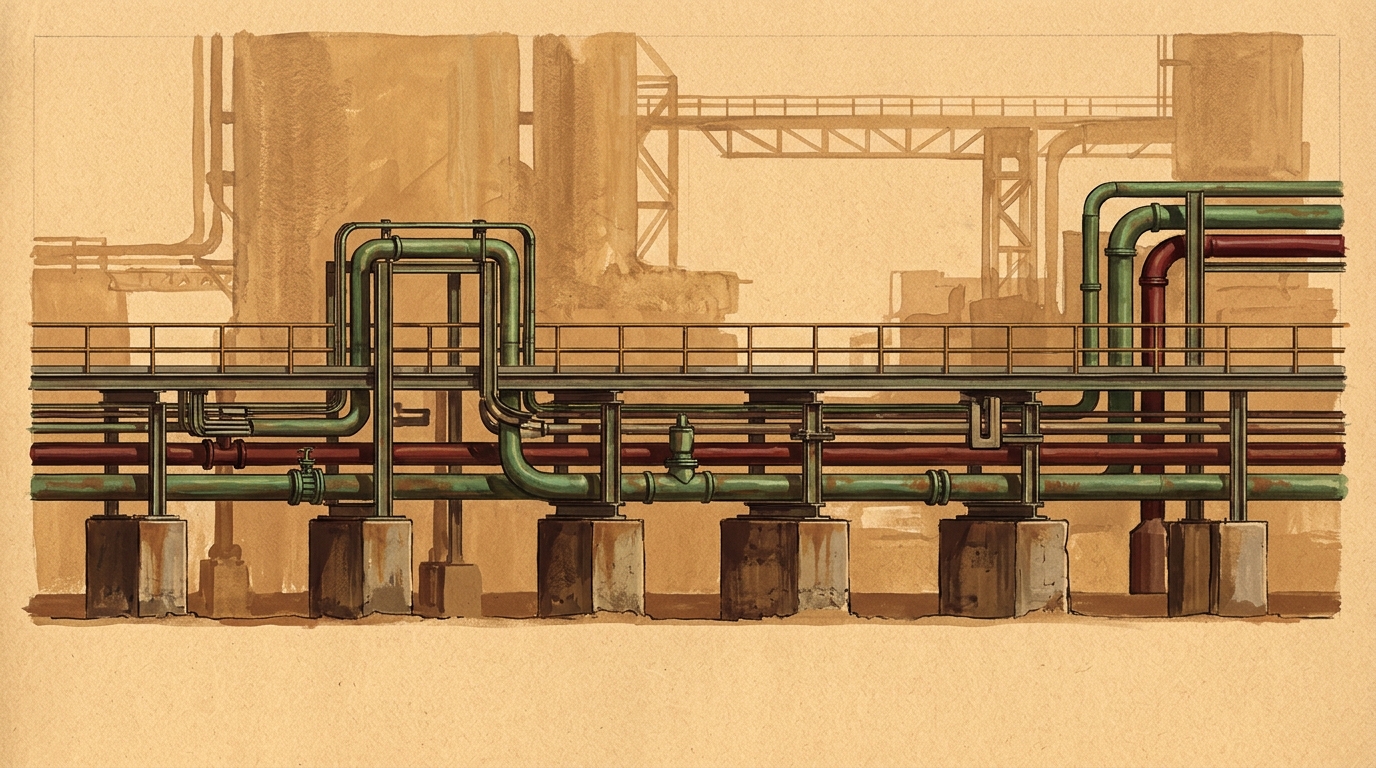 Record the installed arrangement against its own manual before accepting the installation or changing a parameter to hide a discrepancy.
Step 2: Walk the piping against the installed model's manual
Avoid carrying a universal straight-run rule from meter to meter. The Promag 50 operating instructions address installation position, filled-pipe conditions, and inlet and outlet runs. Use the relevant requirements as measured walkdown items, rather than checking a box labelled “installation looks correct.”
For each applicable requirement, record:
- The observed flow direction and sensor orientation.
- The upstream and downstream fittings, valves, pumps, and available straight lengths.
- The expected process condition at the sensor during operation and testing.
- The support, access, and environmental arrangement required by the manual.
- Any deviation, its drawing reference, and its approved disposition.
For the liquid Promag installation, full-pipe and electrode-orientation guidance matters. Do not transfer those requirements indiscriminately to a gas meter or another technology. Likewise, a clamp-on ultrasonic installation requires its own setup evidence; the Prosonic Flow P 500 instructions provide a separate model-specific procedure.
A useful improvement is to replace “straight run checked” with “required arrangement / observed arrangement / evidence.” The longer row is harder to complete casually. It also lets a later reviewer understand why a nearby elbow or valve was accepted.
Close the mechanical gate with the responsible discipline. An instrument checklist should record a pressure-boundary concern and its disposition; it should not silently become approval for pressure testing or process startup.
Step 3: Check electrical connections and save configuration
Treat wiring and measurement configuration as separate checks. The Promag 50 instructions distinguish electrical connection, potential equalization, and commissioning. Your record should show the installed arrangement and the settings used for the assigned measurement duty.
Check terminal assignments against the approved drawing and the exact output option. Record the supply, receiving channel, signal type, and relevant protection requirements. Resolve grounding and potential equalization through the manufacturer's instructions for the installed combination of sensor, pipe, and process. Do not reduce every grounding question to a generic shield rule.
For related background, see cable shielding and grounding and the 4–20 mA loop power budget. Use those guides to understand the signal path while retaining the installed equipment's requirements as the acceptance basis.
Save an as-found configuration before editing. Then record the intended process variable, engineering units, range, flow direction, output assignment, damping, cutoff settings, alarm behavior, and totalizer settings where applicable. Mark unused functions explicitly rather than leaving ambiguous empty cells.
Write down both the device range and the controller's interpretation. “Flow” is not enough: identify mass or volume, units, time base, and any reference conditions used by the application. Have the responsible engineer resolve a mismatch before proceeding.
Step 4: Prove the output path to the receiving system
A forced-output test is useful evidence, but it is not a wet calibration. The Aplisens PEM-1000 manual explicitly separates verification from calibration. Label the electrical test by what it actually exercises, then retain its results alongside the measurement tests.
Use the installed transmitter's output-test procedure under the site's approved control arrangements. Record each commanded output, the independent electrical observation where required, the controller raw value, and the engineering value shown to the operator. Include the approved expected result and tolerance rather than adding a tolerance after seeing the data.
For a simple illustrative linear range of 0–100 m³/h mapped to 4–20 mA, the calculation gives 50 m³/h at 12 mA. That is a worked arithmetic example, not a required range or proof of meter accuracy. Check the actual configured mapping; do not assume every application uses this example.
The PLC scaling guide explains the receiving-system calculation. In the walkdown, retain actual values from the installed channel. Check the channel identity as carefully as the arithmetic.
For a pulse output, record the configured relationship between pulses and quantity, then the receiving counter's interpretation. Keep pulse simulation, live counting, and reference-based measurement results separate. Note any test mode, forced value, or temporary bypass, along with the person responsible for restoring it.
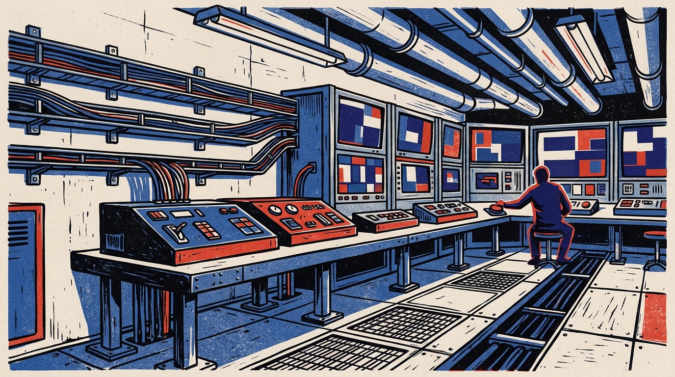 Keep commanded output, measured signal, controller value, and operator indication together so a reviewer can follow the complete test.
Step 5: Check zero before deciding on adjustment
A zero indication needs context. The NEL Coriolis good-practice guide discusses establishing suitable conditions and checking zero stability. Record those conditions first, because adjustment and verification answer different questions.
For the installed technology, find the manufacturer's zero procedure and its prerequisites. Write down the fluid state, stopped-flow evidence, relevant temperature and pressure conditions, observed output, and applicable acceptance criterion. Separate the result as found from any later adjustment and result as left.
Do not use a flowing line as a convenient substitute for the required zero condition. Equally, avoid importing an empty-pipe procedure from an unrelated instrument. The Promag 50 manual and NEL's Coriolis guidance address different equipment and should stay attached to their respective applications.
The NEL guide describes a Coriolis zero-stability assessment using accumulated mass. If that method applies to your installation, record the interval, observed total change, and comparison with the relevant specification. Keep the units explicit. Do not turn its example into an acceptance limit for every meter.
Give zero work two sign-off fields: “conditions established” and “result accepted.” That makes it harder for an attractive zero on the display to conceal an undocumented test setup.
Step 6: Check live flow and close the evidence record
Compare independent evidence where the duty requires measurement acceptance. NIST's water-flow calibration publication describes calibration against reference flow standards. Agreement between the transmitter and controller alone cannot establish that kind of result: they may be using the same measured value.
At authorized operating conditions, record the local indication, transmitted value, receiving-system indication, and relevant diagnostics. Note the process state and whether it was stable enough for the intended test. Investigate disagreement through the recorded installation and configuration before changing calibration-related settings.
For a totalizer comparison, record starting and ending readings, units, direction, interval, and the comparison basis. State whether this is an integration check between devices or a measurement comparison against an independent reference. Establish the allowed deviation in the test plan; this checklist supplies no universal tolerance.
Keep calibration evidence identifiable. Record the meter identity, conditions, range, uncertainty information, and applicability of the certificate or report used for acceptance. The sensor calibration and drift guide gives background for planning later checks.
Close the record with a configuration backup, final test status, open issues, and responsible signatures. Account for every temporary force, bypass, and test mode. If an item remains open, name its owner, required action, and whether the authorized handover permits it.
Frequently asked questions
Does a successful loop test prove flow meter accuracy?
No. A forced output checks the signal path under the conditions tested. It does not compare the measured flow with an independent reference. Record it separately from live-flow and calibration evidence.
Should every flow meter be zeroed during commissioning?
Use the installed model's procedure. Check zero before deciding on adjustment. Record the conditions and as-found result first.
How much straight pipe does a flow meter need?
Take it from the exact manual and arrangement. Record required and actual lengths plus nearby fittings. Escalate deviations.
What should a commissioning handover include?
Keep identity, installation, configuration, test results, applicable calibration evidence, and open issues together. Make each signature's acceptance scope clear.
Does a successful loop test prove flow meter accuracy?
No. A forced output checks the signal path under the conditions tested. It does not compare the measured flow with an independent reference. Record the loop test separately from a live-flow check and from calibration evidence. Specify which test supports each acceptance decision.
Should every flow meter be zeroed during commissioning?
Use the installed model's procedure. Check zero before deciding whether adjustment is necessary. The process conditions matter: a liquid-filled tube with genuinely stopped flow is different from an empty tube or an operating line. Record the conditions and the as-found result before changing a zero setting.
How much straight pipe does a flow meter need?
Take the requirement from the exact meter manual and installation arrangement. Do not copy a number from another meter technology. Record the actual upstream and downstream lengths, the nearby fittings, and the manual reference used to accept them. Escalate deviations before handover.
What should a commissioning handover include?
Keep the meter identity, manual revision, installation checks, configuration backup, signal-path results, zero-check conditions, live-flow observations, and applicable calibration evidence together. List open issues with an owner and disposition. A signature should identify what was accepted and what remains unresolved.
Related Articles