

4-20mA vs 0-10V: Which Analog Signal to Use (and Why)
A 4-20mA loop can run 3,000 ft through a noisy plant floor and land the exact current at the PLC that left the transmitter. Run 0-10V over the same cable and the reading drifts before it gets there. The difference comes down to which physical quantity carries the signal.
Engineers still mix these two standards up, wire loops backward, and can't always tell a real zero from a broken wire. Wiring uncertainty is the tax you pay for guessing. By the end of this guide you'll know the physics behind each standard and how to wire a current loop correctly. You'll also know what live zero protects you from, and a clear rule for picking one signal over the other.
TL;DR: 4-20mA and 0-10V are the two dominant analog signaling standards. In a 4-20mA current loop, the same current flows everywhere in the loop, so it resists wire-resistance voltage drop and shrugs off EMI, and its 4mA "live zero" means a broken wire (0mA) reads as a fault rather than a valid zero. That makes 4-20mA the choice for long, noisy field runs (typically 1,000 to 3,000 ft). 0-10V is cheaper and simpler but loses accuracy over distance and has no live zero, so it fits short in-cabinet runs, LED dimming, and HVAC actuators (usually under 50-300 ft).
This piece pairs naturally with the industrial sensors guide for the bigger picture, and with wiring discrete sensor signals if you're also sorting out NPN/PNP outputs on the same panel. If the device in question is a simple on/off switch rather than an analog transmitter, see proximity sensors for choosing between inductive and capacitive sensing technology.
What Is the Difference Between 4-20mA and 0-10V?
4-20mA encodes a measurement as current, where 4mA equals 0% of range and 20mA equals 100%. 0-10V encodes the same idea as voltage, where 0V equals 0% and 10V equals 100%. That one distinction, current versus voltage, decides everything downstream about noise, distance, and wiring.

Current behaves differently from voltage in a series circuit. In a current loop, the same current flows at every point around the loop no matter what happens to the wire in between. Voltage, by contrast, divides across whatever resistance sits in its path - including the resistance of the cable itself. That's the seed of every advantage 4-20mA has over 0-10V.
The 16mA span (4 to 20) isn't arbitrary. Early loop designers chose 4mA as the zero point instead of 0mA for two reasons: it gives the transmitter a small baseline current to run on, and it creates a "live zero" you can distinguish from a dead wire. That live zero is arguably the single best argument for 4-20mA in the field.
You'll also run into 0-5V and 1-5V variants in older or specialized gear. 1-5V behaves like a voltage cousin of 4-20mA - it has an offset zero too, just without the noise immunity that current provides. 0-5V is a dead-zero signal like 0-10V, just half the span. None of these variants have displaced the two workhorses: 4-20mA dominates field transmitters and process instrumentation, while 0-10V dominates short in-panel signals, lighting control, and HVAC.
Citation capsule: In a 4-20mA loop, current stays equal at every point around the circuit by Kirchhoff's current law, so wire resistance cannot alter what the receiver measures. A 0-10V signal instead divides across that same wire resistance, losing accuracy as cable length grows. The ANSI/ISA-50.00.01 standard and IEC 60381-1 formalize 4-20mA as the process-industry default for exactly this reason (ISA; Acromag).
Why Does 4-20mA Resist Noise and Distance?
4-20mA resists noise and distance loss because the loop current can't be changed by wire resistance. Electromagnetic interference can only ride a fraction of a milliamp on top of a 16mA span. A voltage signal has no such protection - it drops across cable resistance and picks up noise proportional to its own small magnitude.
Current is constant, voltage divides
Picture a current loop as a single series circuit: supply, transmitter, wire, sense resistor, wire, back to supply. Kirchhoff's current law says the current entering that loop equals the current leaving it, at every single point. If you measure 12mA at the receiver, 12mA is passing through the transmitter too - the wire in between is irrelevant to the measurement, regardless of its resistance.
A voltage signal has no equivalent guarantee. Every foot of cable adds resistance, and that resistance eats a slice of the signal before it reaches the receiver. Electrical noise compounds the problem: a 50mV noise spike causes a 5% measurement error on a 1V signal, but only a 0.5% error on a 10V signal (Acromag). Run the same math on a current loop and that 50mV of induced noise barely registers, because it's riding on current, not the voltage the receiver actually measures.
Cable length limits
0-10V signals are typically effective under about 50 ft in electrically noisy plant environments, with a practical maximum around 100-300 ft (Industrial Monitor Direct). Beyond that, voltage drop and EMI pickup start to erode accuracy in ways a control system can't correct for after the fact.
4-20mA, by comparison, typically runs 1,000 to 3,000 ft on 18-24 AWG wire with a standard 24V loop supply (Acromag). That's not a hard ceiling - the actual cable distance a 4-20mA loop can support depends on loop resistance versus available supply voltage, covered in the wiring section below. In practice, it means you can run a current loop from a tank farm to a control room without a repeater; you generally can't do that with 0-10V.
Citation capsule: A 50mV noise spike produces a 5% error on a 1V signal but only 0.5% on a 10V signal, and current loops shrug off the same disturbance almost entirely because current, not voltage, carries the measurement. That's why 4-20mA typically runs 1,000 to 3,000 ft while 0-10V is best kept under roughly 50 ft in noisy plant wiring (Industrial Monitor Direct).
What Is Live Zero and Why Does It Matter?
Live zero means 0% of range is still a nonzero signal - 4mA, not 0mA - so a broken wire or dead transmitter reads 0mA and is unmistakably a fault rather than a valid reading. 0-10V has a dead zero: 0V could mean a real zero measurement or a snapped wire, and the receiver has no way to tell which.
This is the strongest practical argument for 4-20mA, and most comparisons barely mention it. Live zero isn't just an offset chosen for power reasons - it's a built-in diagnostic. Any current below the expected minimum tells you something is wrong before a bad reading ever reaches your process logic.
The NAMUR NE 43 standard formalizes this into precise fault boundaries. The standard measurement range runs 3.8mA to 20.5mA. A reading at or below 3.6mA triggers a low fault, typically indicating dead transmitter electronics or a broken wire. A reading at or above 21.0mA triggers a high fault, typically a short circuit or overrange condition (EE World). Those small guard bands between 3.6-3.8mA and 20.5-21.0mA exist specifically so normal signal noise doesn't false-trigger a fault flag.
0-10V has no equivalent scheme, because a dead 0V reading gives a control system nothing to distinguish diagnostically. Some plants bolt on wire-break detection hardware for voltage loops, but it's an add-on, not something inherent to the signal. That's why safety instrumented systems and process plants lean on 4-20mA and treat NAMUR NE 43 compliance as close to mandatory for critical measurements.
Citation capsule: NAMUR NE 43 defines the valid 4-20mA measurement range as 3.8mA to 20.5mA, with readings at or below 3.6mA flagged as a low fault and readings at or above 21.0mA flagged as a high fault. That live-zero fault detection has no equivalent in a dead-zero 0-10V signal, where 0V and a broken wire look identical to the receiver (EE World).
How Is a Current Loop Wired and Read?
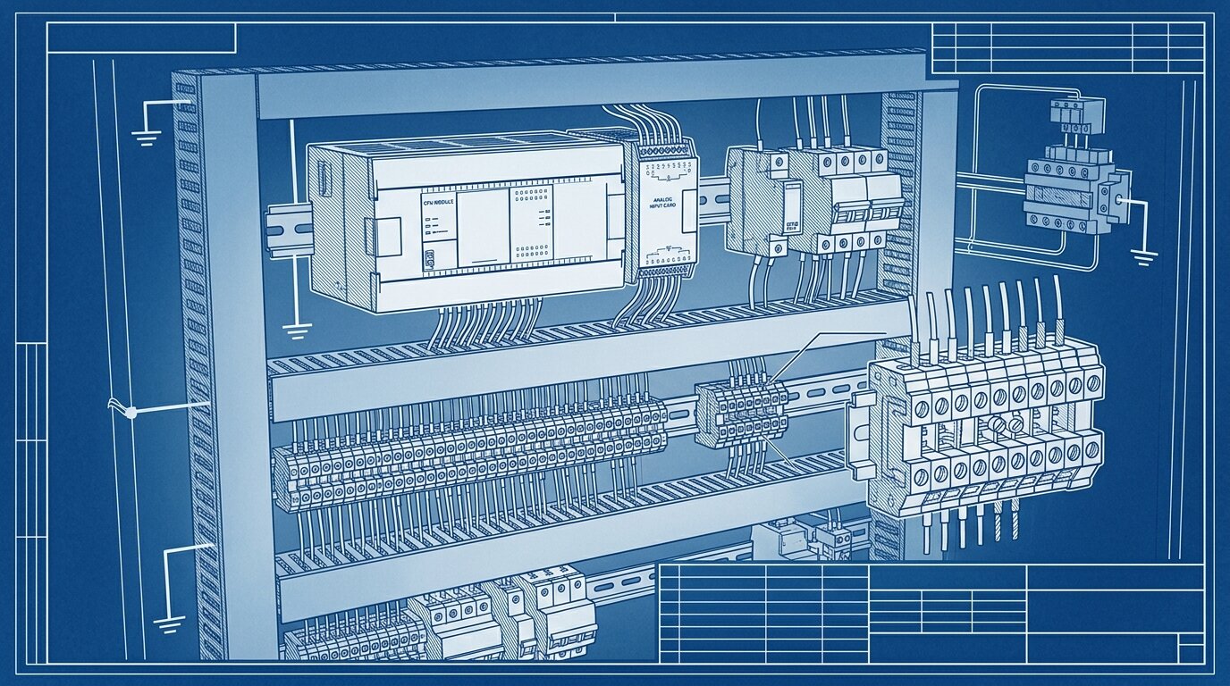
A current loop needs four things: a DC supply (typically 24V), a transmitter that regulates the loop current to match the measured value, the loop wire itself, and a sense resistor at the receiver that converts the current back into a voltage the PLC's analog input card can read.
The 250 ohm sense resistor
PLC analog input cards read voltage far more easily than current, so most installations place a precision 250 ohm sense (or burden) resistor across the input terminals. Ohm's law does the rest: 4mA times 250 ohms equals 1V, and 20mA times 250 ohms equals 5V (Acromag). The result is a clean 1-5V signal riding on top of the loop's 4-20mA current, and the PLC card scales that raw signal back into engineering units.
Other burden values show up too - 500 ohms for a 2-10V span, or smaller values for lower-voltage cards - but 250 ohms to 1-5V is the industry default you'll see on most transmitter and PLC documentation.
Loop resistance and supply voltage
Every element in the loop adds resistance: the wire itself, the sense resistor, and the transmitter's own internal burden. The supply has to push the full 20mA through all of that combined resistance at once, or the loop can't reach its top of range. This available loop-voltage headroom is what caps how far you can run a current loop before you need a higher-voltage supply or heavier-gauge wire.
A typical loop uses a 24V supply and 18-24 AWG wire (Acromag). Longer runs eat more wire resistance, so a run pushing toward 3,000 ft usually needs the heavier end of that gauge range, a supply voltage with real headroom above the minimum the transmitter needs to operate, or both. This is also where active and passive 4-20mA wiring and sinking versus sourcing PLC input terminals matter, much like wiring discrete sensor signals - check whether your input card supplies loop power itself or expects an external supply before you wire anything up.
Citation capsule: A 250 ohm precision sense resistor converts a 4-20mA current loop into a 1-5V signal a PLC analog input can read directly - 4mA times 250 ohms equals 1V, 20mA times 250 ohms equals 5V. Total loop resistance, wire plus sense resistor plus transmitter burden, must stay within what a typical 24V supply can drive at full 20mA current (Acromag).
2-Wire vs 3-Wire vs 4-Wire Transmitters
The wire count on a transmitter describes how it gets power and how isolated its signal is, not some arbitrary spec choice. 2-wire transmitters are loop-powered and cheapest to field-install; 3-wire transmitters use a separate supply with a shared return, which enables displays and diagnostics but opens the door to ground loops; 4-wire transmitters carry fully isolated power and signal for the best noise rejection.
A 2-wire transmitter draws its own operating power from the loop current, typically 3.5-20mA, so the same two conductors carry both power and signal (Forbes Marshall). No separate power wiring is needed in the field, which is exactly why this is the default topology for most pressure, level, and flow transmitters - see how this plays out with pressure transmitters as a related example.
3-wire transmitters add a dedicated power wire but still share a common return with the signal path. That shared return is where ground-loop trouble creeps in, particularly on budget input cards without differential inputs (Forbes Marshall; Industrial Monitor Direct). 4-wire transmitters solve that at the cost of a fourth conductor: fully isolated power and signal circuits with no shared reference, which is the topology you'll see on high-power instruments and anywhere ground-loop risk is unacceptable. The same wire-count logic governs discrete switching sensors too - see 2-wire vs 3-wire vs 4-wire sensor wiring for how it plays out on a simple ON/OFF device instead of a continuous transmitter.
Citation capsule: A 2-wire transmitter powers itself from the loop current alone, drawing roughly 3.5-20mA to run its own electronics without any dedicated power wiring. 3-wire transmitters add a separate supply but keep a shared return that risks ground loops, while 4-wire transmitters isolate power and signal completely for the cleanest noise rejection (Forbes Marshall).
When Should You Use 0-10V Instead?
0-10V wins when the run is short, the environment is electrically quiet, and cost matters more than distance or fault detection. It's also the entrenched standard in a few whole ecosystems - LED dimming and HVAC control chief among them - where switching to 4-20mA would mean fighting the market rather than the physics.
Use 0-10V when:
- Cable run is under roughly 50 ft, with a hard ceiling around 100-300 ft even in favorable conditions
- The environment is low-EMI - no VFDs, contactors, or high-current motor wiring nearby
- Cost is the deciding factor and the receiver has a high-impedance input that needs no sense resistor
- You're dimming LED lighting, where 0-10V is the dominant lighting-control standard
- You're driving HVAC actuators or dampers, where 0-10V is the entrenched convention
- You're integrating with a legacy 0-10V system where converting to 4-20mA isn't worth the retrofit cost
(Industrial Monitor Direct)
0-10V also skips the sense resistor entirely, since the receiver reads voltage natively - one less component and one less thing to spec wrong. For short, quiet, indoor runs, that simplicity is a real advantage, not just a consolation prize.
| Attribute | 4-20 mA | 0-10 V |
|---|---|---|
| Signal carrier | Current | Voltage |
| Noise immunity | High - current is unaffected by wire resistance | Lower - error is proportional to signal voltage |
| Max cable run | Typically 1,000-3,000 ft | Typically under 50-300 ft |
| Fault detection | Live zero - a broken wire reads 0 mA | Dead zero - 0V is ambiguous with a real zero |
| Power | 2-wire loop-powered option available | Needs a separate supply |
| Sense/burden resistor | 250 ohm converts loop current to 1-5V | None needed - receiver reads voltage directly |
| Best for | Long, noisy field runs; process plants | Short in-cabinet runs, LED dimming, HVAC |
4-20 mA wins on distance and fault detection; 0-10V wins on simplicity for short, quiet runs.
Citation capsule: 0-10V is the right call for cable runs under roughly 50 ft in low-EMI environments where cost matters, and it remains the entrenched standard for LED dimming, HVAC actuators, and legacy control systems. It needs no sense resistor and connects directly to high-impedance PLC inputs (Industrial Monitor Direct).
How Do You Avoid Ground Loops and Add HART?
A ground loop happens when two points in a circuit that should share one ground reference instead sit at slightly different potentials, and the resulting circulating current corrupts your reading. Fix it with single-point grounding, signal isolators where multiple ground references are unavoidable, differential or isolated input cards, and shielded cable grounded at one end only. In a hazardous area, the loop also needs intrinsic safety barriers to limit the energy that can reach the field wiring, a separate requirement from grounding practice.
0-10V signals are especially vulnerable here - even a 1-2V difference in ground potential between a sensor and its receiver can generate a circulating current strong enough to corrupt a voltage measurement, particularly on budget single-ended input cards that share a common return. 4-20mA current loops are inherently far more resistant to this failure mode, because the measurement rides on current rather than a voltage difference between two ground points (Industrial Monitor Direct).
A short ground-loop prevention checklist:
- Ground the system at a single point; never at both ends of a shielded cable
- Use signal isolators when a transmitter and receiver genuinely can't share one ground reference
- Prefer differential or isolated analog input cards over single-ended ones for noisy plant areas
- Ground cable shields at one end only, and leave the other end floating
In the field, the mistake I see most is a shield grounded at both ends because it "feels" safer to tie everything down. That second ground point turns the shield into its own conductor, and any potential difference between the two cabinets drives a circulating current straight into the sensor's return path. I've chased that exact fault on a level transmitter that read a slow, cyclical drift no calibration could fix - lifting the shield at the receiver end and grounding it only at the source killed the drift in minutes. It's a five-minute check that gets skipped because the wiring already "looks" correct on the drawing. Our guide to cable shielding and grounding goes deeper into why one-end termination works and how to keep signal cable properly separated from VFD power runs.
4-20mA loops can also carry digital data without disturbing the analog measurement, using the HART protocol. HART superimposes a Frequency Shift Keying signal on the Bell 202 standard - 1200 Hz and 2200 Hz tones - transmitting digital data at roughly 1200 bits per second (Fabrico). Because that FSK waveform is symmetrical around the DC loop current, it averages to exactly zero over time, so the primary 4-20mA analog value passes through undisturbed while diagnostics and configuration data ride the same two wires. It's a neat trick that's kept 4-20mA infrastructure relevant decades after fully digital fieldbuses arrived - devices like modern vibration sensors with analog outputs use exactly this pattern to expose extra diagnostics without adding wiring.
Citation capsule: HART rides a Frequency Shift Keying signal on top of the 4-20mA DC current, using Bell 202 tones at 1200 Hz and 2200 Hz to transmit digital data at roughly 1200 bits per second. Because the FSK waveform is symmetrical, it averages to zero and never disturbs the underlying analog measurement, letting diagnostics travel the same two wires as the process signal (Fabrico).
Frequently Asked Questions
What is the difference between live zero and dead zero?
Live zero (4mA) means 0% output is still a nonzero current, so a broken wire reads 0mA and is unmistakably a fault. Dead zero (0V) means a broken wire and a valid zero reading look identical, so 0-10V systems cannot natively tell them apart (EE World).
How does a 2-wire loop-powered transmitter work?
A 2-wire transmitter draws its own operating power from the loop current itself, typically 3.5-20mA, so the same two conductors carry both power and signal. No separate power wiring is needed in the field (Acromag; Forbes Marshall).
How far can you run a 4-20mA signal?
4-20mA typically runs 1,000 to over 3,000 feet on 18-24 AWG wire with a 24V loop supply, limited only by total loop resistance versus available supply voltage. Actual distance depends on wire gauge and supply headroom (Industrial Monitor Direct; Acromag).
Why is 4-20mA better than 0-10V over long distances?
Current stays constant around a series loop by Kirchhoff's law, so wire resistance cannot change what the receiver measures. A voltage signal divides across that same wire resistance, so it loses accuracy as cable length or noise increases (Acromag).
When should I use 0-10V instead of 4-20mA?
Use 0-10V for short runs under roughly 50 feet in low-EMI environments, where cost matters and a live zero is not required, such as LED dimming, HVAC actuators, and legacy 0-10V equipment (Industrial Monitor Direct).
Conclusion
Current beats voltage over distance for one physics reason: loop current stays constant regardless of wire resistance, while a voltage signal divides across it. The 4mA live zero turns that same current into a built-in broken-wire detector, something 0-10V's dead zero can't do. Wire count on a transmitter is a choice about power and isolation, not a random spec field. Those advantages are why 4-20mA remains a standard industrial signal.
None of that makes 0-10V obsolete. For short, quiet, cost-driven runs - in-cabinet signals, LED dimming, HVAC actuators - 0-10V is still the simpler, cheaper pick, and fighting that convention for no reason wastes money. Choose by distance, noise, fault-detection need, and cost, in that order, and you'll rarely wire the wrong one.
Analog signal transmitters aren't the only sensors that need this kind of wiring discipline - load cells and strain gauges run into the same noise and grounding tradeoffs at their own millivolt-level outputs, much like a thermocouple does before its signal gets conditioned into a 4-20mA loop. For the bigger picture on how these signals fit into a plant's sensing layer, start with the industrial sensors guide.
What is the difference between live zero and dead zero?
Live zero (4mA) means 0% output is still a nonzero current, so a broken wire reads 0mA and is unmistakably a fault. Dead zero (0V) means a broken wire and a valid zero reading look identical, so 0-10V systems cannot natively tell them apart (EE World).
How does a 2-wire loop-powered transmitter work?
A 2-wire transmitter draws its own operating power from the loop current itself, typically 3.5-20mA, so the same two conductors carry both power and signal. No separate power wiring is needed in the field (Acromag; Forbes Marshall).
How far can you run a 4-20mA signal?
4-20mA typically runs 1,000 to over 3,000 feet on 18-24 AWG wire with a 24V loop supply, limited only by total loop resistance versus available supply voltage. Actual distance depends on wire gauge and supply headroom (Industrial Monitor Direct; Acromag).
Why is 4-20mA better than 0-10V over long distances?
Current stays constant around a series loop by Kirchhoff's law, so wire resistance cannot change what the receiver measures. A voltage signal divides across that same wire resistance, so it loses accuracy as cable length or noise increases (Acromag).
When should I use 0-10V instead of 4-20mA?
Use 0-10V for short runs under roughly 50 feet in low-EMI environments, where cost matters and a live zero is not required, such as LED dimming, HVAC actuators, and legacy 0-10V equipment (Industrial Monitor Direct).
Related Articles

