

2-Wire vs 3-Wire vs 4-Wire Sensor Wiring: Which to Use
A 2-wire proximity sensor can leak 0.5 to 1.5 mA of current into a PLC input even when it reads "off" (Click2Electro, via notebook c5a023f0). On an older relay panel that current was harmless. On a modern high-impedance DC input card, it can be enough to hold the input ON long after the target has moved away.
That single fact explains most of the confusion around sensor wiring. The number of wires on a sensor isn't a cosmetic spec - it decides where the power path and the signal path sit relative to each other, and that decision has real consequences at the PLC terminal block. Get it wrong and you inherit voltage drop, phantom signals, or a wiring bill you didn't need to pay.
This guide walks through how 2-wire, 3-wire, and 4-wire sensors actually work, where each one breaks down, and how to pick the right configuration before you pull cable. For the broader picture of how these sensors fit into a plant's measurement layer, see the complete guide to industrial sensors.
TL;DR: 2-wire sensors share power and signal on one pair, which costs several volts of drop and 0.5-1.5 mA of leakage current that can false-trigger sensitive PLC inputs. 3-wire sensors add a dedicated power wire and cut leakage to zero. 4-wire sensors separate power and signal (or add a second output) for the cleanest, most isolated wiring. Source: notebook c5a023f0 (Click2Electro; TI current-loop references).
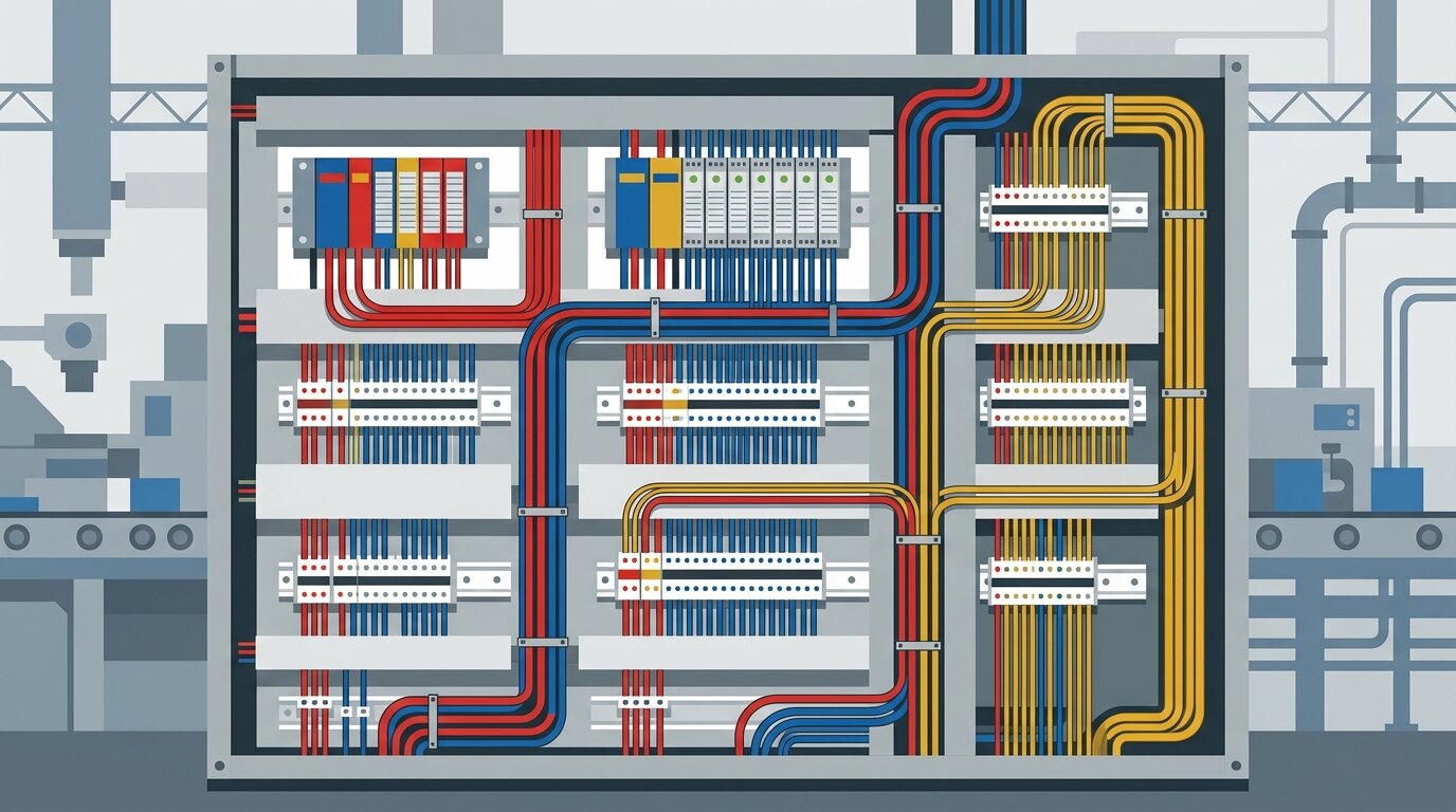
Organized terminal wiring keeps the power path and signal path visibly separate before they ever reach the PLC input card.
What Do the Wires in a Sensor Actually Do?
Every sensor wire does one of two jobs: it carries power to the sensor's electronics, or it carries the switched signal back to the controller. The number of wires tells you whether those two jobs share a conductor or run on separate ones - that's the entire distinction, before you ever look at NPN or PNP.
A 2-wire sensor forces both jobs onto the same pair. It sits in series with the load like a mechanical switch, and its own electronics siphon a sliver of that same current to stay alive. A 3-wire sensor gives power its own dedicated pair and lets the signal wire switch independently. A 4-wire sensor goes further, giving the signal itself a fully separate pair - or a second output wire for redundancy.
Framing it this way - power path versus signal path - makes NPN and PNP easier to understand later, because those terms only describe which direction current flows on the signal wire once it's separated from power. Reading the notebook's source material side by side, most 2-wire versus 3-wire versus 4-wire confusion traces back to one habit: writers explain wire count and switching logic as if they were the same topic. They aren't. Wire count is about where the return path sits; NPN/PNP is about which rail that return path connects to.
How Does 2-Wire Sensor Wiring Work?
A 2-wire sensor's voltage budget stacks a roughly 5V receiver burden, the wire's own resistance drop, and about 7V of internal overhead the sensor needs just to run its electronics (notebook c5a023f0, citing Texas Instruments current-loop transmitter references). All three subtract from whatever supply voltage you started with, before the load circuit sees a single volt.
The sensor sits directly in series with the load, exactly like a mechanical switch would. There's no dedicated power wire - brown and blue carry both the sensor's own operating current and the switched load current together. That's what makes 2-wire wiring so cheap to install: two terminals, no separate power run, done.
The Voltage-Drop Budget
Note that these voltage-budget and loop-resistance limits describe 2-wire analog 4-20mA current-loop transmitters. A discrete 2-wire proximity switch shares the same series-loop principle, but it's governed by its leakage and burden specs rather than an explicit resistor budget.
The receiver burden alone eats about 5V on a 250-ohm sense resistor carrying 20 mA. Add wire resistance and the sensor's own roughly 7V internal minimum. A 24V supply has surprisingly little headroom left for the load itself (notebook c5a023f0). On a 12V supply, that budget can eat the whole thing.
Loop Resistance and Distance Limits
Total loop resistance caps out at 250 ohms on a 24V supply, or 600 ohms on a 30V supply, before the loop can no longer reach full current (notebook c5a023f0). Practically, a 2-wire loop on shielded twisted-pair cable holds up to roughly 1,000 meters before that resistance budget runs out (notebook c5a023f0). Longer runs need heavier wire, a higher supply voltage, or a different configuration entirely.
Why Do 2-Wire Sensors Have Leakage Current?
2-wire sensors must let 0.5 to 1.5 mA flow through the signal line even while "off," because that's the only power source their internal electronics have (Click2Electro, via notebook c5a023f0). Older relay-based panels never noticed this. Modern PLC input cards, with their much higher input impedance, sometimes do.
Where the Leakage Current Comes From
A 2-wire sensor has no dedicated supply wire, so it draws its standby power directly from the same signal line the PLC is watching. That current has to keep flowing - the sensor's internal circuitry would shut down without it. It typically lands between 0.5 mA and 1.5 mA (notebook c5a023f0), consistent with NAMUR EN 60947-5-6 input design guidance (notebook c5a023f0). Some high-impedance DC input cards register ON at just 1-2 mA. That puts the leakage uncomfortably close to a false trigger. The NAMUR interface standard (EN 60947-5-6) exists precisely because low-current proximity switches need a formally defined ON/OFF boundary rather than an ad hoc PLC threshold.
I ran into this on a 2-wire inductive proximity sensor watching a conveyor guard interlock. The target - a steel flag on the guard - would swing clear, the sensor LED would drop out, and the panel's PLC input would sit there reading ON for another two or three seconds before finally clearing. Nothing in the program explained it; the ladder logic was fine, the sensor tested fine on the bench. The input card just had enough impedance that the sensor's own 1.2 mA of standby leakage was enough to hold the input above its turn-on threshold after the target left. It wasn't a bad sensor or a bad program - it was a 2-wire device leaking current into a card that was more sensitive than the relay panel it replaced.
Fixing a Ghost-ON Signal
The standard fix is a bleeder (or load) resistor, typically 2.2 to 3 kilohms, wired from the PLC input terminal to common (Click2Electro, via notebook c5a023f0). That resistor gives the leakage current a path to ground that doesn't run through the input's sensing circuit, pulling the terminal voltage back below the ON threshold. On that conveyor guard, a 2.2 kilohm bleeder killed the ghost signal in about ten minutes. Where the panel design allows it, swapping to a 3-wire sensor removes the leakage path altogether instead of just working around it.
How Does 3-Wire Sensor Wiring Work?
3-wire sensors have zero leakage current on the signal wire when off, because a dedicated power wire means the sensor never needs to borrow standby current from the line the PLC is watching (Click2Electro, via notebook c5a023f0). That single change removes the ghost-ON failure mode completely - not partially, completely.
Brown carries +24V DC supply, blue carries 0V return, and black carries the switched signal - three jobs, three wires, no overlap. The output transistor still has a small drop when it conducts: about 0.3-0.7V for a bipolar junction transistor output, or 0.1-0.5V for a MOSFET output (notebook c5a023f0). Either way, it's a fraction of a volt, not several volts.

A field-mounted proximity sensor and its cable run from guard to junction box - the wire count decided long before the cable ever reaches this point.
NPN (Sinking) Output
An NPN 3-wire sensor's output transistor pulls the signal wire toward 0V when it activates - it sinks current. The load sits between +24V and the sensor's black wire, and current flows down through the sensor to ground only while the target is present. NPN needs a PLC input wired as sourcing, with its common terminal tied to +24V.
PNP (Sourcing) Output
A PNP 3-wire sensor's output transistor pushes the signal wire toward +24V when it activates - it sources current. The load sits between the sensor's black wire and 0V, and current flows from the supply down through the load only while the target is present. PNP needs a PLC input wired as sinking, with its common terminal tied to 0V.
What Is NPN vs PNP (Sinking vs Sourcing)?
NPN and PNP describe which rail a 3-wire sensor's switched output connects to once power and signal have already been separated - NPN sinks to 0V, PNP sources from +24V. This is the same switching-logic question that trips up engineers wiring NPN and PNP proximity sensors directly to a PLC, and it applies identically whether the sensor is inductive, capacitive, or photoelectric.
The practical trap is that a mismatched sensor and input produce no fault code - the input just never activates. PLC input circuits also apply 5-20 milliseconds of noise-rejection filtering on top of whatever the sensor itself can switch (notebook c5a023f0), so even a correctly matched sensor won't register instantaneously. That filtering rarely matters for guard interlocks or part-present sensing, but it's worth knowing before you chase a "slow" input that's actually behaving as designed.
How Does 4-Wire Sensor Wiring Work?
A 4-wire configuration gives power its own dedicated pair and the signal its own fully separate pair, so voltage drop on the supply side never touches the accuracy of the signal (notebook c5a023f0, current-loop wiring sources). That total independence is the whole point of paying for a fourth conductor.
Some 4-wire digital sensors extend this idea with dual switched outputs instead of a second power pair - one normally open, one normally closed - so a safety relay or monitoring input can watch both states at once. If one output fails to change state when the other does, the mismatch itself becomes the fault signal. That redundancy is why 4-wire sensors show up on guard interlocks and other safety-related switching, even though the base wiring concept - independent power and independent signal - is the same one used in the power-and-isolation tradeoff in analog transmitters.
Where a shared ground reference between two panels isn't reliable, a dedicated signal isolator with galvanic isolation breaks that ground connection entirely rather than relying on the sensor's own wiring to do it. That's a separate piece of hardware from the sensor, but it solves the same class of problem 4-wire wiring is aiming at: keeping one circuit's voltage drop from bleeding into another's signal.
2-Wire vs 3-Wire vs 4-Wire: Full Comparison
| Attribute | 2-Wire | 3-Wire | 4-Wire |
|---|---|---|---|
| Power path | Shared with signal | Dedicated pair | Dedicated pair |
| Leakage current (off) | 0.5-1.5 mA | Zero | Zero |
| Output voltage drop (on) | Several volts (loop budget) | BJT 0.3-0.7V, MOSFET 0.1-0.5V | BJT 0.3-0.7V, MOSFET 0.1-0.5V |
| Practical distance | Up to ~1,000 m (shielded pair) | Longer runs supported by dedicated power | Longest, power and signal fully decoupled |
| Loop resistance limit | 250 ohm at 24V, 600 ohm at 30V | Not applicable (no shared loop) | Not applicable |
| Typical use | Retrofits, simple series switching | Standard NPN/PNP discrete sensing | Safety interlocks, dual-output, isolated wiring |
Source: notebook c5a023f0 (Click2Electro leakage-current analysis; TI and current-loop wiring references).
The pattern across every row is the same: the more the power path and signal path separate, the fewer side effects each one has on the other. That's the entire tradeoff, expressed six different ways.
Which Wiring Configuration Should You Choose?
Choose based on how sensitive your PLC input is and how much you value simplicity over signal purity - a 2-wire sensor into a high-impedance input is the single riskiest combination in this whole comparison, and it's also the cheapest to wire. Match the sensor to the input card, not just to the budget.
| If you need... | Choose | Why |
|---|---|---|
| Cheapest retrofit into an old relay panel | 2-wire | Simple series switching; older relay panels tolerate the leakage current |
| Standard discrete sensing on a modern PLC | 3-wire | Zero leakage current removes the ghost-ON failure mode entirely |
| Safety interlock or redundant monitoring | 4-wire | Dual outputs or fully isolated power and signal for fault-tolerant wiring |
| Long cable run with a shared ground concern | 3 or 4-wire, plus a dedicated signal isolator | Removes shared-ground and voltage-drop interactions |
When 2-Wire Still Makes Sense
2-wire earns its keep when you're retrofitting an old relay-based panel that already tolerates leakage current, or when running a fourth wire is genuinely impractical. Add a bleeder resistor at the input if the replacement PLC card is more sensitive than the equipment it replaced.
When 3-Wire Is the Default
3-wire is the right call for essentially any new discrete sensing point on a modern PLC. Zero leakage current means no ghost-ON risk, and the wiring is no more complicated to pull than 2-wire once you're already running a power conductor to the panel.
When 4-Wire Earns Its Extra Wire
4-wire is worth the fourth conductor when a single point of failure isn't acceptable - guard interlocks, redundant position confirmation, or any circuit feeding a safety relay. It's also the right call when the sensor and PLC genuinely can't share a clean ground reference; for that specific problem, troubleshooting current-loop noise the same way you'd troubleshoot 4-20mA loop noise applies just as directly to discrete wiring.
Frequently Asked Questions
What is the difference between 2-wire and 3-wire sensors?
A 2-wire sensor shares one pair of wires for power and signal, so it drops several volts across the loop and leaks 0.5-1.5 mA even when off. A 3-wire sensor uses a dedicated power pair plus a separate signal wire, cutting leakage current to zero (Click2Electro, via notebook c5a023f0).
Why do 2-wire sensors have voltage drop?
A 2-wire sensor has no dedicated power wire, so it borrows its operating voltage from the loop it switches. The budget stacks a roughly 5V receiver burden, wire resistance drop, and about 7V of internal transmitter overhead, all subtracted from the supply before the load sees anything (notebook c5a023f0).
What is leakage current in a 2-wire sensor?
Leakage current is the 0.5-1.5 mA a 2-wire sensor must draw through the signal line even when "off," just to keep its internal electronics alive. Modern high-impedance PLC inputs can register ON at 1-2 mA, so that leakage alone can false-trigger the input (Click2Electro, via notebook c5a023f0).
When do you use a 4-wire sensor?
Use a 4-wire sensor when you need a fully independent power pair and a fully independent signal pair, or dual complementary outputs for safety monitoring. It costs one extra wire but removes any voltage-drop or leakage interaction between the supply and the switched signal.
Can you connect a 2-wire sensor to a PLC input?
Yes, but check the input impedance first. High-impedance DC input cards can misread 2-wire leakage current (0.5-1.5 mA) as a valid ON signal. A 2.2-3 kilohm bleeder resistor from the input terminal to common shunts that leakage safely to ground (Click2Electro, via notebook c5a023f0).
Conclusion
Wire count tells you where the power path and signal path sit - together on a 2-wire sensor, separated on a 3-wire sensor, fully independent (or doubled) on a 4-wire sensor. That's the whole framework, and it explains the leakage current, the voltage drop, and the distance limits in one shot.
For most new discrete sensing points on a modern PLC, 3-wire is the safe default: it removes the ghost-ON risk that 2-wire leakage current creates, at almost no added cost or complexity. Reserve 2-wire for retrofits into tolerant relay panels, and reserve 4-wire for anywhere a single point of failure genuinely isn't acceptable. For the discrete-switching side of this decision - matching NPN or PNP to your PLC input type - see the companion guide to wiring NPN and PNP proximity sensors. For the analog side of the same power-path-versus-signal-path question, 4-20mA vs 0-10V covers how the same tradeoffs play out on continuous measurement signals.
What is the difference between 2-wire and 3-wire sensors?
A 2-wire sensor shares one pair of wires for power and signal, so it drops several volts across the loop and leaks 0.5-1.5 mA even when off. A 3-wire sensor uses a dedicated power pair plus a separate signal wire, cutting leakage to zero (Click2Electro, via notebook c5a023f0).
Why do 2-wire sensors have voltage drop?
A 2-wire sensor has no dedicated power wire, so it borrows its operating voltage from the loop it switches. The budget stacks a roughly 5V receiver burden, wire resistance drop, and about 7V of internal transmitter overhead - all subtracted from the supply before the load sees anything (notebook c5a023f0).
What is leakage current in a 2-wire sensor?
Leakage current is the 0.5-1.5 mA a 2-wire sensor must draw through the signal line even when "off," just to keep its internal electronics alive. Modern high-impedance PLC inputs can register ON at 1-2 mA, so that leakage alone can false-trigger the input (Click2Electro, via notebook c5a023f0).
When do you use a 4-wire sensor?
Use a 4-wire sensor when you need a fully independent power pair and a fully independent signal pair, or dual complementary outputs for safety monitoring. It costs one extra wire but removes any voltage-drop or leakage interaction between the supply and the switched signal.
Can you connect a 2-wire sensor to a PLC input?
Yes, but check the input impedance first. High-impedance DC input cards can misread 2-wire leakage current (0.5-1.5 mA) as a valid ON signal. A 2.2-3 kilohm bleeder resistor from the input terminal to common shunts that leakage safely to ground (Click2Electro, via notebook c5a023f0).
Related Articles

