
Selecting Sensors for Hazardous Locations: ATEX/IECEx Certification Guide
Select a hazardous-location sensor against its complete installation requirements, rather than stopping at an ATEX or IECEx logo. The European Commission's ATEX guidance distinguishes complete equipment from components and identifies conditions attached to certificates. Those distinctions affect what you can install (ATEX Guidelines, fifth edition, April 2024, §47).
This guide gives controls engineers and procurement teams a document-led selection process. It covers the approval route, equipment category, temperature conditions, certificate schedules, and the installation record. It does not classify your plant or approve a circuit design. Start with the site's documented hazardous-area requirements and have the responsible engineer resolve any mismatch before ordering.
TL;DR: Match the sensor's documents to the installation, including the area category, atmosphere, temperatures, and certificate conditions. Commission guidance associates Category 2 equipment with gas Zones 1 and 2 and dust Zones 21 and 22. An approval label alone does not complete the selection; retain the certificate schedule and installation instructions.
For circuit background, see intrinsic safety and IS barriers.
Which certification route does the project require?
ATEX and IECEx documents serve different purposes. Directive 2014/34/EU provides the EU product-conformity framework, while IECEx operates a certification scheme. IECEx's own comparison guide explains their relationship; an IECEx certificate does not replace the ATEX conformity process for the EU market (IECEx 01A, edition 3, 2018).
Write down the destination market and the project's required approvals before comparing sensor models. If the purchase specification requests both ATEX and IECEx documentation, ask the supplier for both sets for the exact variant quoted. Resolve any difference between the quotation, declaration, and certificate. Do not assume the product family name settles it.
For ATEX equipment, distinguish the manufacturer's EU Declaration of Conformity from an EU-type examination certificate where applicable. The Commission guidance describes the declaration and product-identification requirements in Article 14 and Annex X. It also describes the certificate's identification and safety information in §182. These documents serve related roles; they are not interchangeable (ATEX Guidelines).
The IECEx comparison publication describes the equipment-scheme relationship as an Ex Test Report plus a Quality Assessment Report supporting an IECEx Certificate of Conformity. It also describes the public electronic certificate system. As a procurement check, record the certificate number and verify the certificate record, rather than accepting a cropped logo from a catalogue (IECEx 01A, §8).
How do you match the area to the equipment category?
Use the site's area classification to select the equipment category. The Commission's 2024 guidance gives a normal zone/category correspondence: Category 1 covers Zones 0/20, Category 2 covers Zones 1/21, and Category 3 covers Zones 2/22. It also shows the less demanding zones covered by higher-protection categories (ATEX Guidelines, §133, Table 5).
| ATEX category | Gas zones in the guidance's correspondence | Dust zones in the guidance's correspondence |
|---|---|---|
| 1 | 0, 1, 2 | 20, 21, 22 |
| 2 | 1, 2 | 21, 22 |
| 3 | 2 | 22 |
This is the guidance's normal correspondence. Section §133 also describes variation based on detailed risk assessment and possible differences under national implementation. Have the responsible engineer establish the applicable selection for the site; the table alone does not approve an installation (ATEX Guidelines).
The gas or dust designation matters alongside the category number. The guidance's marking examples distinguish II 1 G for non-mining gas/vapour/mist equipment from II 1 D for dust equipment. Don't shorten a purchase requirement to a category number that leaves the atmosphere unspecified (ATEX Guidelines, Table 6).
Equipment Protection Levels are another set of terms you will encounter on documents. Pepperl+Fuchs's older Manual Explosion Protection describes Ga/Gb/Gc for gas and Da/Db/Dc for dust. Use it as background terminology, rather than treating those labels as legal definitions from the ATEX product directive. This guide does not use an EPL table to approve an installation (Pepperl+Fuchs manual, distributor-hosted copy, §4.1).
A useful selection sheet has separate entries for the site's zone, the required atmosphere designation, and the offered equipment marking. Separate entries expose incomplete supplier responses. An “Ex approved” checkbox leaves the responsible engineer without the details to compare.
Which temperature and atmosphere details need checking?
Read the temperature conditions for the actual sensor configuration. Commission guidance notes that electrical products are normally designed and tested for an ambient range of −20°C to +40°C under harmonised standards; products outside that range require additional marking and testing as appropriate. That guidance is not a substitute for the offered device's limits (ATEX Guidelines, §29).
Record the required gas or dust group from the site's specification, then compare it with the offered marking. For dust terminology, COELBO's manufacturer guide distinguishes IIIA combustible flyings, IIIB non-conductive dust, and IIIC conductive dust. This is technical background for reading the documents; use the actual certificate and site assessment for selection (COELBO, Principles of Explosion Protection, combustible-dust subdivision table).
Keep ambient temperature, process temperature, and permissible equipment surface temperature in separate rows. A temperature-probe example shows why: JUMO's RTD instructions calculate the permissible probe-tip temperature from the temperature class, a safety deduction, power input, and the protection-tube constant. Its worked T4 example gives a maximum medium temperature of 90°C under the stated conditions (JUMO RTD instructions, thermal data and calculation example).
That 90°C result belongs to JUMO's example, not to every T4 sensor. The manual uses a 135°C T4 surface-temperature limit, subtracts 5 K, then subtracts the heating contribution of 0.5 W × 80 K/W. The result is 130°C − 40 K = 90°C. Preserve those assumptions when discussing the example; do not copy its result into another product's specification (JUMO RTD instructions).
For the measurement-element choice, PT100 versus PT1000 selection is a separate comparison to complete alongside the approval review. List the mechanical arrangement, measuring insert, connecting cable, terminal head, and intended temperatures in the supplier enquiry. Ask the supplier to identify the assessed configuration.
What do X and U mean on a certificate?
An X suffix identifies specific conditions of use; a U suffix identifies an Ex component needing further evaluation before installation. The Commission guidance compares these cases in Table 2. Read the schedule and instructions, rather than treating either suffix as an administrative detail (ATEX Guidelines, §47).
For equipment with X, copy each applicable condition into the installation review and assign someone to show how it is met. Ask for the full certificate and schedule, rather than only its first page. If the quotation omits a condition or the intended configuration is unclear, return the question to the supplier before approving the order.
For an ATEX component with U, the guidance describes an attestation of conformity and assembly instructions, with final assessment as part of the complete equipment. A component certificate is not evidence that the component is ready for standalone field installation. Buying it for incorporation can be appropriate; the remaining assessment needs an owner (ATEX Guidelines, Table 2).
 Carry each applicable certificate condition into the installation review and record how the proposed sensor configuration meets it.
A certificate-reading example
The bound Rotork-hosted certificate, Baseefa10ATEX0026 Issue 15, is dated 2 November 2022 and covers Bifold Type 27/77 solenoid operators. It is not a sensor certificate. It illustrates the document structure: manufacturer and product identity, applied standards, markings, schedule, drawings, and revision history. Its specific-conditions section says “None” (certificate and schedule).
Use that structure as a reading exercise, not a source of sensor ratings. For your purchase, record the corresponding fields from the sensor's own certificate. Check the offered type against the schedule, retain the issue you reviewed, and note any open configuration questions. Keep that record with the certificate.
What belongs in an intrinsically safe installation record?
Make the interconnection review part of the procurement handoff. Commission guidance calls for technical parameters significant for Ex safety in an EU-type examination certificate. Use that information as an input to the design review, rather than treating a sensor approval as a completed installation record (ATEX Guidelines, §182).
For system background, Pepperl+Fuchs's older manufacturer manual describes interconnected equipment documented by a system description. It discusses energy limitation in apparatus and connecting cables, explaining why the cable and interface belong in the review (Pepperl+Fuchs manual, §§4.1 and 7.5.4).
Ask the responsible designer to identify the sensor, associated apparatus, cable data, and applicable installation instructions in one record. This article does not supply a universal loop-approval calculation. Use the current certificates and applicable installation requirements for the particular design; a worked example in a manufacturer guide cannot approve a different combination.
MTL/Cooper Crouse-Hinds's Intrinsic Safety Solutions gives an illustrative interface/transmitter comparison. Its example compares 28 V output with a 30 V input limit, 93 mA with 120 mA, and 650 mW with 1 W. It then accounts for the field device when determining cable allowances (MTL guide, distributor-hosted copy, Table 4.1/Figure 4.1).
For capacitance, that example starts with 83 nF and subtracts 3 nF to leave 80 nF for cable. These are the guide's example values, not a generally available cable budget. Use the example to check whether the calculation accounts for the field device and cable. Obtain the actual limits and conditions from the selected equipment documentation (MTL guide).
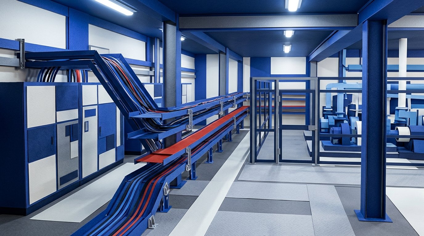 Keep the sensor, interface, cable assumptions, and installation conditions together so the complete proposed interconnection can be reviewed.
The 4–20 mA loop power-budget calculation addresses another part of the design handoff. Keep its operating-power worksheet alongside the Ex documentation, with each review's purpose clearly identified. Avoid using one completed worksheet as a sign-off for questions it did not examine.
What should procurement retain before ordering?
Build a file that identifies the offered product and the documents used to assess it. The Commission guidance's Annex X sets out declaration identification and traceability information; §182 describes identification and safety parameters in an EU-type examination certificate. Use those fields to organise the review, obtaining the certificate where applicable (ATEX Guidelines).
Before releasing the order, retain:
- Site requirements: area classification, atmosphere, required approvals, and intended temperatures.
- Supplier identification: exact model, options, offered marking, and configuration drawing where needed.
- ATEX documentation: applicable declaration or component attestation, instructions, and relevant certificate with its full schedule.
- IECEx documentation when specified: certificate number and the record reviewed.
- Installation evidence: condition-by-condition review and the interconnection record where intrinsic safety is used.
- Open questions: named owner, required supplier response, and a decision before purchase release.
For each requirement, put the supplier's evidence in the next column and the reviewer in the last. Leave an unresolved item visibly open. This is a suggested working method, not a prescribed statutory form. The record should identify the configuration the team reviewed.
For enclosure ingress requirements, use the separate IP ratings guide alongside the certificate review. Then send procurement the exact approved configuration and the document list together. Ask for a fresh technical review if the supplier proposes a different variant rather than letting a substitution inherit the earlier sign-off.
Frequently asked questions
Does IECEx replace ATEX for an EU project?
No. IECEx's 2018 comparison guide distinguishes its certification scheme from the ATEX framework under Directive 2014/34/EU. An IECEx certificate does not replace the EU conformity process. Request the applicable ATEX documents for the offered equipment, plus IECEx documentation when the project requires it (IECEx 01A).
Can Category 2 equipment be selected for Zone 0?
Under the Commission guidance's normal correspondence, Category 2 equipment covers gas Zones 1 and 2; Category 1 covers Zone 0. Section §133 also describes variation based on detailed risk assessment and possible differences under national implementation. Have the responsible engineer check the applicable rules and the site's assessment; a category marking alone does not settle the selection (ATEX Guidelines, Table 5 and §133).
Is a U-suffix component ready to install by itself?
No. The Commission guidance's Table 2 describes an Ex component as incomplete and requiring further evaluation. It distinguishes the component's attestation and assembly instructions from the documents for complete equipment. A component may be purchased for incorporation, but that does not complete the assessment of the final equipment (ATEX Guidelines).
Does T4 specify a sensor's process-temperature limit?
Do not use the class alone as the process-temperature limit. JUMO's instructions illustrate the distinction: their worked T4 example uses the 135°C surface limit, a safety deduction, and calculated heating to reach a 90°C medium limit. That result applies to the stated example, not every T4 sensor (JUMO RTD instructions).
Does IECEx replace ATEX for an EU project?
No. IECEx's 2018 comparison guide distinguishes its certification scheme from the ATEX framework under Directive 2014/34/EU. An IECEx certificate does not replace the EU conformity process. Request the applicable ATEX documents for the offered equipment, plus IECEx documentation when the project requires it (IECEx 01A).
Can Category 2 equipment be selected for Zone 0?
Under the Commission guidance's normal correspondence, Category 2 equipment covers gas Zones 1 and 2; Category 1 covers Zone 0. Section §133 also describes variation based on detailed risk assessment and possible differences under national implementation. Have the responsible engineer check the applicable rules and the site's assessment; a category marking alone does not settle the selection (ATEX Guidelines, Table 5 and §133).
Is a U-suffix component ready to install by itself?
No. The Commission guidance's Table 2 describes an Ex component as incomplete and requiring further evaluation. It distinguishes the component's attestation and assembly instructions from the documents for complete equipment. A component may be purchased for incorporation, but that does not complete the assessment of the final equipment (ATEX Guidelines).
Does T4 specify a sensor's process-temperature limit?
Do not use the class alone as the process-temperature limit. JUMO's instructions illustrate the distinction: their worked T4 example uses the 135°C surface limit, a safety deduction, and calculated heating to reach a 90°C medium limit. That result applies to the stated example, not every T4 sensor (JUMO RTD instructions).

