Sensors Edge Hub Logo
PT100 vs PT1000: Which RTD to Use (and Why)
Industrial Sensors · 16 min read · Jul 15, 2026 · By Rihards Niparts

PT100 vs PT1000: Which RTD to Use (and Why)

A PT100 and a PT1000 measure temperature with the same platinum element and the same standard curve. Run both down a long 2-wire cable, though, and only one of them keeps its accuracy - the other drifts off by degrees. That gap isn't a flaw in either sensor. It's Ohm's law.

Most engineers reach for PT100 out of habit, wire it 2-wire because it's convenient, and lose accuracy to lead resistance without ever noticing. This guide covers the resistance and sensitivity difference, the lead-error math, and the 2/3/4-wire tradeoff. It also covers IEC 60751 accuracy classes and a clear rule for picking the right RTD and wiring for the accuracy you need.

Read more in the industrial sensors guide and RTD vs thermocouple for how RTDs compare to the other major temperature-sensing technology.

TL;DR: A PT100 reads 100 ohms at 0 C; a PT1000 reads 1000 ohms. Both are platinum, both follow the same IEC 60751 curve, and both change resistance by about 0.385% per degree - a PT100 moves ~0.385 ohms per degree, a PT1000 moves ~3.85 ohms per degree. That 10x-higher signal is the whole point: a 1 ohm lead adds about 2.6 C of error to a PT100 but only about 0.26 C to a PT1000. Use PT1000 for 2-wire, long cable, and low-power jobs; use PT100 for established 3-wire and 4-wire process loops where accuracy and interchangeability matter, per Beamex (2026).

What Is the Difference Between PT100 and PT1000?

Both are platinum resistance thermometers that follow the same IEC 60751 curve; a PT100 reads 100 ohms at 0 C and a PT1000 reads 1000 ohms at 0 C. Otherwise they behave identically - PT1000 just has 10x the resistance and 10x the resistance change per degree, per Beamex (2026).

The "Pt" marks the element as platinum. The number is the nominal resistance in ohms at 0 C. Both numbers share one physical relationship: platinum's resistance rises with temperature at a standardized coefficient, alpha, of 0.003851 per C under IEC 60751 (2026). That single number makes RTDs interchangeable across manufacturers.

Because the alpha is identical, the sensitivity scales directly with the base resistance. A PT100 changes by about 0.385 ohms per degree C; a PT1000 changes by about 3.85 ohms per degree C, per HT-Heater and Beamex (2026). Multiply the resistance and the sensitivity both by ten, and the sensor's underlying physics hasn't changed - only the size of the electrical signal it produces.

PT100 and PT1000 aren't "cheap version, precise version." They're the same measurement principle on two different resistance scales. The choice between them comes down to how that scale interacts with your wiring and power budget, not the accuracy of the platinum element itself.

PT100 and PT1000 Resistance vs Temperature (IEC 60751) Same curve shape, one order of magnitude apart - PT100 plotted on the axis; PT1000 reads 10x these values 0 100 200 300 350+ ohms Resistance (ohms, PT100 scale) -200 C 0 C 200 C 400 C 600 C 100 ohms (PT100) / 1000 ohms (PT1000) at 0 C 18.5 ohm 313.7 ohm PT1000 reads 10x these values at every temperature (185 ohm to 1000 ohm to 3130 ohm) Source: IEC 60751, Beamex (2026)
Both PT100 and PT1000 follow the same IEC 60751 curve - PT1000 is simply 10x the resistance at every temperature.

Both sensors share the same standardized range: -200 C to +850 C under IEC 60751, and the same set of accuracy classes apply to both. Nothing about the curve shape, the classes, or the physical stability of platinum changes when you move from a 100 ohm element to a 1000 ohm element.

Citation capsule: A PT100 reads 100 ohms and a PT1000 reads 1000 ohms at 0 C - both platinum RTDs on the identical IEC 60751 curve with alpha = 0.003851 per C, per Beamex and IEC 60751 (2026). Sensitivity scales with resistance: a PT100 moves about 0.385 ohms per degree, a PT1000 about 3.85 ohms per degree. The two sensors are electrically identical in behavior; only the resistance scale differs, which changes how lead resistance and excitation current affect the reading, not how accurate the platinum element is.

Why Does PT1000 Reduce Lead-Wire Error?

A temperature reading from an RTD is really a resistance measurement, and the lead wires add their own resistance in series with the sensor. Because that lead resistance is a much smaller fraction of a 1000 ohm PT1000 than of a 100 ohm PT100, it matters roughly 10x less on the higher-resistance sensor.

The Lead-Error Math

In an uncompensated 2-wire hookup, the instrument can't tell sensor resistance from lead resistance - it just sees the total. Every 1 ohm of lead resistance reads as about 2.6 C of false error on a PT100, but only about 0.26 C on a PT1000, per HT-Heater (2026). That's a direct consequence of the sensitivity numbers above: divide 1 ohm by 0.385 ohm/C for the PT100, and by 3.85 ohm/C for the PT1000.

2-Wire Lead-Resistance Error: PT100 vs PT1000 Error grows with lead resistance - and it is 10x smaller on a PT1000 0 C 3 C 6 C 9 C 12 C 0 ohm 1 ohm 2 ohm 3 ohm 4 ohm Lead resistance (ohms, one lead) 2.6 5.2 7.8 10.4 1.04 PT100 (2.6 C per ohm) PT1000 (0.26 C per ohm) 3-wire and 4-wire wiring drive this error toward zero Source: HT-Heater (2026)
Lead-wire error grows with lead resistance, and it is 10x smaller on a PT1000 than on a PT100 (2.6 C vs 0.26 C per ohm), per HT-Heater.

Why It Matters Over Distance

The error scales directly with cable length and wire gauge, since both drive up the total lead resistance. A short jumper barely registers. A 50 or 100 meter run of thin-gauge copper, though, can add several ohms - and on a 2-wire PT100 that's several degrees of error the instrument has no way to detect or subtract.

In the field, I've seen a PT100 on a long 2-wire run read a couple of degrees high for months before anyone questioned it. The process looked "close enough" until a calibration check flagged the offset, and re-terminating it as 3-wire pulled the reading back in line. Nobody had done anything wrong - the 2-wire wiring wasn't accurate enough for that cable run.

This is why PT1000 makes 2-wire and long cable runs practical. The sensor isn't more accurate at the element - it's less sensitive to a source of error that 2-wire wiring can't cancel.

Citation capsule: Lead-wire resistance in a 2-wire RTD circuit reads as false temperature error, and PT1000's 10x higher resistance cuts that error 10x compared to PT100. A 1 ohm lead adds about 2.6 C of error on a PT100 but only about 0.26 C on a PT1000, per HT-Heater (2026). The error grows with cable length and wire gauge, which is why PT1000 - not extra wiring - is often the simplest fix for long 2-wire runs.

2-Wire vs 3-Wire vs 4-Wire RTD Wiring: What's the Difference?

The wiring configuration is how you deal with lead resistance: 2-wire ignores it entirely, 3-wire cancels it by assuming matched leads, and 4-wire (Kelvin) eliminates it completely by separating the current and sense paths, per Beamex and IEC 60751 (2026).

2-wire is the simplest and cheapest option. Two conductors carry both the excitation current and the measurement signal, so any lead resistance adds directly onto the sensor resistance and the instrument has no way to separate the two. It's fine for short runs or loose tolerances; it's a liability on anything long.

3-wire adds a third conductor running the full length of the cable. The instrument uses that third leg to measure lead resistance on one side. It subtracts an equivalent amount from the total reading, assuming both current-carrying leads are the same gauge and length. It's the industrial workhorse for a reason - it gets most of the way to eliminating lead error at a modest wiring cost.

2-Wire vs 3-Wire vs 4-Wire RTD Connections How each wiring scheme handles lead-wire resistance 2-Wire RTD Instrument R_lead R_lead Both R_lead values add directly to the sensor reading lead resistance adds to the reading 3-Wire RTD Instrument R_lead R_lead sense Sense lead measures one R_lead and subtracts it out cancels lead resistance (matched leads) 4-Wire (Kelvin) RTD Instrument current current sense sense Sense pair carries no current, so its R_lead never enters the reading eliminates lead resistance (Kelvin) R_lead = resistance of one lead wire, same physical cable in all three cases Source: Beamex, IEC 60751 (2026)
2-wire lets lead resistance add to the reading; 3-wire cancels it with a matched sense lead; 4-wire Kelvin wiring eliminates it entirely.

That "assuming matched leads" clause is where 3-wire compensation fails. If one leg is a different gauge, a different length from a splice or repair, or routed through a different junction box, the compensation no longer cancels cleanly and a residual error creeps back in. I've traced a "drifting" 3-wire loop back to exactly that. A repair years earlier had spliced in a shorter run of wire on one leg. The mismatch showed up as a steady few tenths of a degree offset, and no amount of recalibration could fully remove it until the leads were replaced to match.

4-wire (Kelvin) sidesteps the matching problem entirely. Two wires carry the excitation current; two separate wires measure the voltage drop across the sensor with essentially no current flowing through them, so their resistance doesn't factor into the reading. It's the most accurate option and the standard for lab-grade and reference measurements, at the cost of two extra conductors.

Citation capsule: RTD wiring configurations handle lead resistance three different ways. 2-wire adds lead resistance directly to the reading; 3-wire cancels it by subtracting a matched-lead estimate; 4-wire (Kelvin) eliminates it by separating current and sense paths entirely, per Beamex and IEC 60751 (2026). 3-wire compensation depends on the two current leads matching in gauge and length - a common source of residual error when a lead has been spliced or repaired.

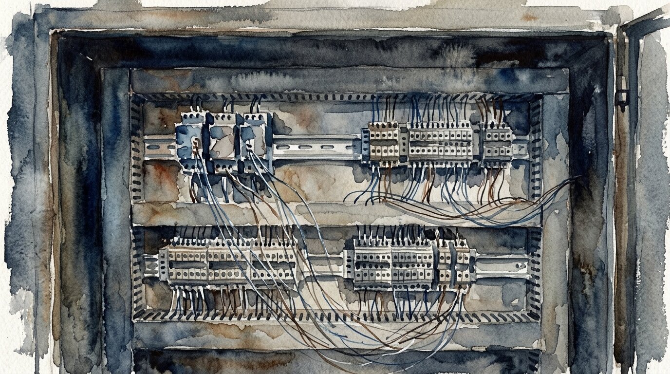
An industrial control cabinet with RTD transmitters on a DIN rail and terminal blocks where the sensor leads land

How Accurate Is Each RTD - What Do IEC 60751 Classes Mean?

Accuracy is graded by IEC 60751 tolerance classes - AA, A, B, and C - each defined as a formula in degrees C that widens as temperature moves away from 0 C, and the class you can actually claim in practice depends on how the RTD is wired.

Class B, the most common industrial grade, is about +/-(0.3 + 0.005|t|) C. Class AA, the tightest standard class, is about +/-(0.1 + 0.0017|t|) C, per IEC 60751 (2026). Class A sits between the two. Both PT100 and PT1000 share the same class definitions - the class is a property of the platinum element and manufacturing tolerance, not the resistance value.

Spec sheets rarely mention this: Class A and Class AA effectively require 3-wire or 4-wire connection. A Class AA tolerance is tight - a fraction of a degree near 0 C - so even modest 2-wire lead resistance error swamps it. Buying a Class AA element and wiring it 2-wire over any real distance throws that accuracy away before the reading reaches the instrument.

Choose PT1000 when:

  • 2-wire wiring is the only practical option
  • Cable runs are long
  • The device is battery-powered or otherwise power-constrained
  • Fast, cost-effective thin-film construction fits the application
  • Budget favors simpler wiring over an extra conductor

Choose PT100 when:

  • The installation is an established 3-wire or 4-wire process loop
  • Maximum accuracy and interchangeability are required
  • Wide temperature range or wire-wound construction is needed
  • Existing transmitters and instruments are already configured for PT100

Citation capsule: IEC 60751 defines RTD accuracy in tolerance classes: Class AA at about +/-(0.1 + 0.0017|t|) C, Class B at about +/-(0.3 + 0.005|t|) C (2026). Class A and AA effectively require 3-wire or 4-wire wiring, since 2-wire lead resistance error is large enough to exceed those tighter tolerances outright. The wiring you choose, not just the sensor you buy, determines which class you can honestly claim on the installed loop.

How Do Self-Heating and Excitation Current Compare?

Measuring an RTD means pushing a small current through it, and that current generates heat in the element - self-heating - which shows up as a falsely high reading. PT1000 needs less current for the same usable signal, so it self-heats less than a PT100 under the same conditions.

PT100 measurement current runs up to about 1 mA under IEC 60751 guidance, while PT1000 typically uses about 0.1-0.5 mA, per Beamex (2026). Because a PT1000 already produces a larger voltage drop per degree at a given current, less current is needed to get a clean, readable signal - and less current through the element means less resistive self-heating.

Lower excitation current matters most in still air, low-conductivity environments, or gas streams, where the sensor has less opportunity to shed the small amount of heat it generates. It also matters for anything running on a battery or energy-harvested power supply, where every microamp of continuous draw counts against runtime. Keeping excitation current as low as the instrument allows is good practice on either sensor type, but PT1000 gives you more headroom by design.

Citation capsule: RTD self-heating comes from the excitation current used to measure resistance. PT100 typically runs up to about 1 mA, while PT1000 typically runs about 0.1-0.5 mA for an equivalent signal, per Beamex (2026). The lower current requirement reduces self-heating error and cuts power draw, which is why PT1000 fits low-power and battery-powered instrumentation better than PT100 under otherwise identical conditions.

Thin-Film vs Wire-Wound: How Are RTDs Built?

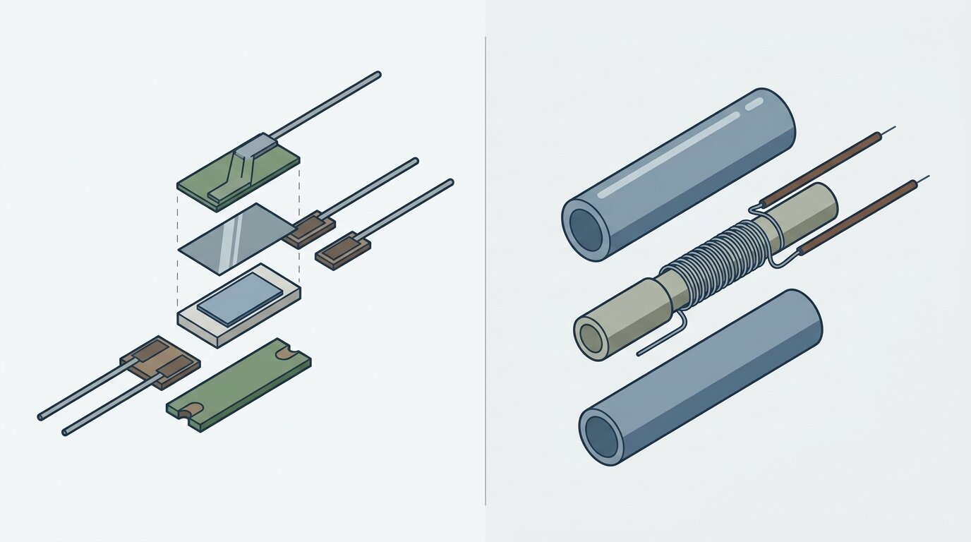
RTDs come in two constructions - thin-film, a platinum film deposited on a small ceramic chip, and wire-wound, a coil of fine platinum wire in a ceramic or glass housing - and the choice affects temperature range, response speed, and stability, not the underlying accuracy class.

Thin-film elements are typically limited to about 400-500 C, while wire-wound elements handle up to about 600 C, per Endress+Hauser and Tempsens (2026). The standard's full defined range is -200 C to +850 C for both, but the physical construction, not the standard, sets the practical ceiling for a given part.

Two RTD element constructions side by side, a thin-film platinum element on a ceramic chip and a wire-wound platinum coil inside a ceramic tube

Thin-film construction is smaller, cheaper to manufacture, and responds faster to temperature changes. That's why most PT1000 elements on the market are thin-film - it fits the low-cost, fast-response, moderate-temperature niche PT1000 tends to serve. Wire-wound construction is more mechanically delicate but more thermally stable over time and over a wider range, which is part of why it remains common in high-accuracy PT100 elements built for demanding process-control duty.

Neither construction changes the IEC 60751 curve or the accuracy class formula. It changes how long the element survives at temperature, how fast it responds to a step change, and how tightly it holds calibration over years of thermal cycling.

When Should You Use PT100 vs PT1000?

Pick based on wiring and power constraints, not on habit: PT1000 wins 2-wire, long-cable, and battery-powered jobs because it shrinks lead error and current draw 10x; PT100 stays the standard for established 3-wire and 4-wire process loops where the highest accuracy and cross-vendor interchangeability matter.

If you're running a new 2-wire installation over any real distance - a remote outdoor sensor, a long run to a skid-mounted transmitter, anything battery-powered - PT1000 removes most of the accuracy penalty 2-wire wiring would otherwise cost you. If you're working inside an existing 3-wire or 4-wire process-control loop, especially one built around PT100 transmitters and instrumentation, there's rarely a reason to switch. The wiring is already doing the job that PT1000's resistance advantage would otherwise buy you.

Both sensor types typically feed a transmitter that converts the resistance reading into a standard 4-20mA signal for the control system. The choice between PT100 and PT1000 is independent of how the reading reaches the PLC or DCS. If the process calls for a different measurement principle rather than a different RTD, RTD vs thermocouple covers when thermocouples take over. The same "match the sensor to the wiring and environment" logic applies more broadly - see how to select a sensor for that framework applied elsewhere.

PT100 vs PT1000 at a Glance

The table below is the fast reference: same platinum, same curve, one order-of-magnitude difference in resistance that cascades into every other tradeoff between the two sensors.

Attribute PT100 PT1000
Resistance at 0 C 100 ohm 1000 ohm
Sensitivity ~0.385 ohm/C ~3.85 ohm/C
Lead error per 1 ohm of lead ~2.6 C ~0.26 C
Typical measurement current up to ~1 mA ~0.1-0.5 mA
Self-heating higher current, more lower current, less
Common construction wire-wound or thin-film usually thin-film
IEC 60751 range -200 to +850 C -200 to +850 C
Best for established 3/4-wire process control, highest accuracy 2-wire, long cables, low-power/battery

Both share the IEC 60751 curve and the temperature coefficient alpha = 0.003851/C.

Frequently Asked Questions

What is the difference between PT100 and PT1000?

A PT100 reads 100 ohms at 0 C and a PT1000 reads 1000 ohms at 0 C - both are platinum RTDs on the same IEC 60751 curve. PT1000 simply has 10x the resistance and 10x the signal per degree, per Beamex (2026).

What is the difference between 2-wire, 3-wire, and 4-wire RTD wiring?

2-wire lets lead resistance add directly to the reading; 3-wire uses a third conductor to cancel it, assuming matched leads; 4-wire (Kelvin) separates current and sense pairs to eliminate lead resistance entirely, per Beamex and IEC 60751 (2026).

How big is RTD lead-wire error?

1 ohm of lead resistance adds about 2.6 C of error on a PT100 but only about 0.26 C on a PT1000, per HT-Heater (2026). The error scales directly with cable length and wire gauge.

Why is PT1000 better for battery-powered or long-cable jobs?

PT1000 needs roughly 0.1-0.5 mA of excitation current versus up to about 1 mA for a PT100, so it draws less power and self-heats less, per Beamex (2026). Its 10x higher resistance also makes 2-wire and long runs practical without a big accuracy penalty.

What are IEC 60751 accuracy classes?

IEC 60751 Class AA tolerance is about +/-(0.1 + 0.0017|t|) C and Class B is about +/-(0.3 + 0.005|t|) C, with Class A in between. Class A and AA effectively require 3-wire or 4-wire wiring, because 2-wire lead error swamps the tolerance (2026).

Conclusion

PT100 and PT1000 are the same platinum element on the same IEC 60751 curve. The choice isn't about which one is "more accurate" - it's about which resistance scale fits your wiring and power budget. PT1000's 10x resistance cuts lead-wire error 10x and needs less excitation current, which is why it wins 2-wire, long-cable, and low-power installations. PT100 remains the established standard for 3-wire and 4-wire process-control loops where the highest accuracy and cross-vendor interchangeability matter. Either way, the wiring you choose decides which IEC 60751 class you can claim on the installed loop.

For the rest of temperature sensing, read the complete industrial sensors guide, RTD vs thermocouple, and thermocouple types explained.

Frequently Asked Questions

What is the difference between PT100 and PT1000?
A PT100 reads 100 ohms at 0 C and a PT1000 reads 1000 ohms at 0 C - both are platinum RTDs on the same IEC 60751 curve. PT1000 simply has 10x the resistance and 10x the signal per degree, per Beamex (2026).
What is the difference between 2-wire, 3-wire, and 4-wire RTD wiring?
2-wire lets lead resistance add directly to the reading; 3-wire uses a third conductor to cancel it, assuming matched leads; 4-wire (Kelvin) separates current and sense pairs to eliminate lead resistance entirely, per Beamex and IEC 60751 (2026).
How big is RTD lead-wire error?
1 ohm of lead resistance adds about 2.6 C of error on a PT100 but only about 0.26 C on a PT1000, per HT-Heater (2026). The error scales directly with cable length and wire gauge.
Why is PT1000 better for battery-powered or long-cable jobs?
PT1000 needs roughly 0.1-0.5 mA of excitation current versus up to about 1 mA for a PT100, so it draws less power and self-heats less, per Beamex (2026). Its 10x higher resistance also makes 2-wire and long runs practical without a big accuracy penalty.
What are IEC 60751 accuracy classes?
IEC 60751 Class AA tolerance is about +/-(0.1 + 0.0017|t|) C and Class B is about +/-(0.3 + 0.005|t|) C, with Class A in between. Class A and AA effectively require 3-wire or 4-wire wiring, because 2-wire lead error swamps the tolerance (2026).