Sensors Edge Hub Logo
Intrinsic Safety and IS Barriers, Explained
Industrial Sensors · 21 min read · Jul 15, 2026 · By Rihards Niparts

Intrinsic Safety and IS Barriers, Explained

A tank sensor can sit close enough to the vapor space that a bad spark matters immediately. Intrinsic safety keeps the few volts on its wires too weak to ignite that atmosphere, even if something inside the circuit fails.

Engineers specifying instruments for a hazardous area hit Zener versus galvanic barriers, entity parameters, and a maze of zone and gas-group labels right away. Get one wrong and you've got a real ignition risk, or a loop rejected at inspection. This guide covers the energy-limitation principle, the two barrier types, entity-parameter matching, hazardous-area zones, and when to choose intrinsic safety over an explosion-proof enclosure.

TL;DR: Intrinsic safety (IS) protects a hazardous area by making it impossible for the circuit to store or release enough energy to ignite the surrounding gas, even under fault, by capping voltage, current, and power. A barrier in the safe area does the limiting: a Zener barrier needs a high-integrity earth (under about 1 ohm), a galvanic isolated barrier does not. The loop is only safe if the barrier's entity parameters match the field device and cable (MTL AN9003, 2026).

This piece pairs with the industrial sensors guide for the wider signal-wiring picture, and with signal isolators if you're already comparing isolation methods for the same panel.

What Is Intrinsic Safety?

Intrinsic safety limits the electrical and thermal energy in a hazardous-area circuit below what's needed to ignite the specific gas or dust present. No spark and no hot surface ever carries enough energy to start a fire, even under fault conditions (MTL AN9003, 2026).

Fire needs three things at once: fuel, oxygen, and enough ignition energy to start a reaction. In a hazardous area you can't remove the fuel (the process gas) or the oxygen (the air), so IS attacks the third leg. It keeps the circuit's stored and released energy so low that no spark, arc, or hot component can supply the energy the gas needs.

That cap is specific. Power is typically limited to around 1.2 to 1.3 watts, which keeps a component's surface temperature under the T4 (135 C) classification threshold - cool enough that even a continuously hot surface, not just a momentary spark, stays below the gas's autoignition point (MTL AN9003, 2026).

Most people skip past the phrase "even under fault." IS isn't rated for normal operation only. Every certified IS circuit is analyzed with faults deliberately applied - an open diode, a shorted resistor, a broken connection - and it still has to stay under the ignition-energy limit. That separates a genuinely intrinsically safe design from one that just runs at low voltage most of the time.

Citation capsule: Intrinsic safety limits a circuit's electrical and thermal energy below the minimum ignition energy of the surrounding atmosphere, and it must hold that limit even with faults deliberately applied - an open diode, a shorted resistor, a broken wire. Power is typically capped around 1.2 to 1.3 watts, which keeps the surface temperature under the T4 (135 C) classification most instruments need (MTL AN9003, 2026). The decision rule: if a circuit can't store or release enough energy to ignite the gas under any single or double fault, it qualifies as intrinsically safe - anything less is just a low-voltage circuit that happens to look safe.

Why Does Gas Group Matter - Ignition Energy?

Different gases ignite at wildly different energies, and IS limits are set to the worst case present in the area. Hydrogen needs only about 20 microjoules to ignite; methane needs roughly 160 microjoules, eight times more energy. That's why hydrogen-class areas demand the tightest circuit limits (MTL AN9003 / Pat Kruger, 2026).

That gap is why gas groups exist. Group IIA covers propane and similar hydrocarbons, the easiest to protect against. Group IIB covers ethylene, a step up in sensitivity. Group IIC covers hydrogen and acetylene, the hardest group and the one every serious IS designer treats as the reference case, because a barrier rated for IIC automatically covers the easier groups too.

Temperature class (T1 through T6) is a separate, complementary rating. It caps the maximum surface temperature any part of the equipment can reach, from T1 (450 C) down to T6 (85 C), matched against the gas's autoignition temperature. A circuit can pass its energy limit and still fail on temperature class if a component runs hot under fault, so both checks matter independently.

A barrier's data sheet states both a gas group and a temperature class certification, and neither substitutes for the other. Specifying "IS" without checking both against the actual gas in your plant is a common shortcut that inspection eventually catches.

Citation capsule: Hydrogen needs only about 20 microjoules of ignition energy, against roughly 160 microjoules for methane, which is why Group IIC (hydrogen and acetylene) sets the toughest bar for IS circuit design and Group IIA (propane) the easiest (MTL AN9003 / Pat Kruger, 2026). Decision rule: a barrier certified for IIC automatically covers IIB and IIA, so specifying to the worst gas present, not the average one, is the safer default when the plant handles more than one gas type.

Zener Barriers vs Galvanic Isolators - Which Barrier Type?

The energy-limiting device comes in two types. A Zener barrier clamps voltage with shunt diodes and limits current with a series resistor and fuse - simple and cheap, but it needs a high-integrity intrinsically-safe earth. A galvanic isolated barrier passes the signal through a transformer or optocoupler, so it needs no dedicated earth at all (G.M. International, 2026).

Attribute Zener barrier Galvanic isolated barrier
How it limits Shunt Zener diodes + series resistor + fuse Transformer or optical isolation
Needs a dedicated IS earth Yes, under about 1 ohm No
Field device grounding Must be isolated from ground May be grounded normally
Noise rejection Lower Better
Maintenance Fuse can blow; earth continuity must be checked None of that overhead
Cost / size Lower, simpler Higher
Best for / trend Simple loops, budget-constrained sites New installs, flexibility, no dedicated earth

A Zener barrier is cheaper and simpler but depends on a sub-1-ohm dedicated earth; a galvanic isolated barrier costs more but eliminates that earth-fault risk entirely.

Zener barriers (and the earth requirement)

A Zener barrier is a passive network: shunt Zener diodes clamp excess voltage, a series resistor limits fault current, and a fuse protects the diodes themselves. When a fault pushes voltage above the clamp point, the diodes divert that excess current to a dedicated intrinsically-safe earth.

That earth isn't optional wiring hygiene; it's structural to how the barrier works. It needs a high-integrity connection to the equipotential bonding system or the plant's power earth, with a path resistance under roughly 1 ohm, wired through dedicated conductors - typically one 4 mm2 copper conductor, or two separate redundant 1.5 mm2 conductors for reliability (Power & Cables, 2026). The field device and cable screen must also stay isolated from ground, since the barrier's whole safety case depends on fault current having exactly one path: down that dedicated earth, not through the field wiring.

In the field, I've traced a "safe" Zener-barrier loop that had quietly stopped being safe. The dedicated IS earth conductor had corroded at a junction box years after commissioning, and nothing in normal operation ever exercised it enough to reveal the fault. The barrier still passed current normally; it just had no working path to divert a fault to. An insulation and continuity check on the earth conductor at every inspection cycle isn't paperwork - it's the one thing standing between "certified" and "actually intrinsically safe" on a Zener installation.

Galvanic isolated barriers

A galvanic isolated barrier achieves the same energy limitation without ever creating a direct electrical path between the safe and hazardous sides. The signal crosses through a transformer, a relay, or an optocoupler instead, so there's no fault current to divert and no dedicated IS earth requirement (G.M. International, 2026).

That has real downstream consequences. The field device can be grounded normally rather than kept floating, cable screens don't need the same isolation discipline, and the barrier rejects electrical noise noticeably better than a Zener network, since there's no shared conductive path for interference to ride in on. Galvanic units cost more up front, but the earth-fault headaches and the ongoing maintenance of a sub-1-ohm bonding system disappear entirely - exactly why new installations increasingly default to galvanic over Zener (G.M. International, 2026).

Zener barriers still have a place: cheaper per channel, simpler to troubleshoot, and perfectly adequate where the plant already maintains a solid IS earthing system. The fuse inside a Zener barrier is also a wear item worth tracking; a blown fuse takes the loop down with no warning beyond the failed reading. After chasing one too many earth-continuity problems across a multi-cabinet installation, one plant I worked with simply moved its barrier standard to galvanic for new projects - it costs more per channel but removes an entire category of nuisance faults from the maintenance list.

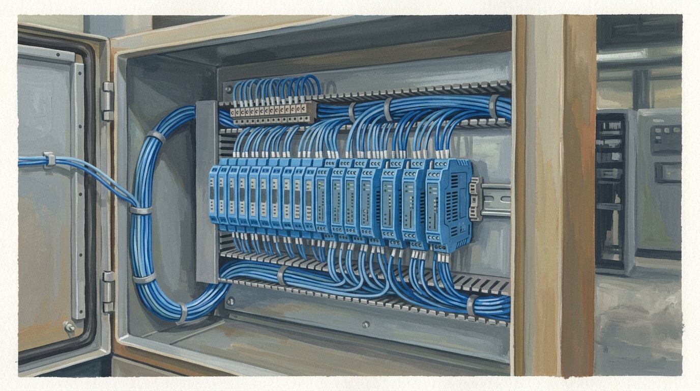
A bank of DIN-rail intrinsic-safety barrier modules in a safe-area marshalling cabinet, each channel protecting one hazardous-area loop

Citation capsule: A Zener barrier clamps fault voltage with shunt diodes and diverts the excess current to a dedicated intrinsically-safe earth, which must hold a path resistance under about 1 ohm through a 4 mm2 conductor or two redundant 1.5 mm2 conductors, with the field device kept isolated from ground (Power & Cables, 2026). A galvanic isolated barrier uses transformer or optical isolation instead, needs no dedicated IS earth, tolerates a grounded field device, and rejects noise better - which is why new installations trend galvanic (G.M. International, 2026). Decision rule: choose Zener where a solid IS earth already exists and cost per channel matters most; choose galvanic to eliminate earth-fault maintenance and improve noise immunity.

How Does the Barrier Limit Energy - the Architecture?

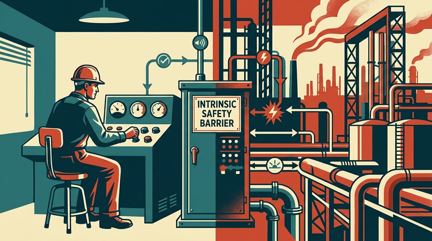
The barrier sits in the safe area, physically and electrically, between the control system and the field wiring that runs into the hazardous zone. Everything downstream - cable, connectors, field device - is limited to whatever energy the barrier is certified to pass, so the hazardous-side circuit can never receive more, no matter what happens upstream.

How the IS Barrier Limits Energy Across the Divide Everything on the field side is capped at whatever the barrier is certified to pass SAFE AREA HAZARDOUS AREA safe area | hazardous area Control system PLC IS barrier safe-area boundary Field device transmitter / sensor Uo, Io, Po (limited energy) Ui, Ii, Pi cable stores energy: Cc, Lc IS earth high-integrity IS earth, less than about 1 ohm (Zener only)
The IS barrier sits in the safe area and limits the voltage, current, and power crossing into the hazardous area, so the field circuit can never receive enough energy to ignite the gas.

The intrinsic-safety barrier sits at the boundary between the safe area and the hazardous area, limiting the energy that can cross into the explosive atmosphere

That dividing line is not just a location on a drawing - it's where the certified barrier's rated output becomes the hard ceiling for the entire downstream circuit. Everything on the field side of that line, including any junction boxes, is designed around never exceeding what the barrier can deliver.

The cable connecting the two isn't a passive bystander either. Real cable stores energy of its own, as capacitance and inductance, and that energy has to be accounted for alongside the barrier's own output limits - covered in the entity-parameters section next. A long or unusually capacitive cable run can eat into the safety margin even when the barrier and the device individually check out.

One category of field device gets an exception. "Simple apparatus" - a passive component like a thermocouple, an RTD, or a switch contact that can't store or generate meaningful energy on its own - can go into an IS circuit without its own IS certificate, since it contributes nothing to the energy budget. That's part of why RTD signal loops and thermocouples show up so often on IS-rated instrument loops without extra paperwork of their own.

Citation capsule: The barrier's certified output sets a hard ceiling on the energy the hazardous-side circuit can ever receive, since it sits at the boundary between the safe area and the field wiring. The connecting cable is not passive - it stores capacitance and inductance that count against the same safety budget as the barrier and field device (MTL AN9003, 2026). Decision rule: a passive "simple apparatus" (a switch contact, thermocouple, or RTD element) that can't store or generate meaningful energy needs no IS certificate of its own, but anything active on the field side does.

Entity Parameters - How Do You Match the Barrier to the Device?

An IS loop is only safe if the barrier truly cannot deliver more energy than the field device and cable can safely absorb. You prove that on paper by matching entity parameters: the barrier's rated Uo, Io, and Po must each be less than or equal to the device's rated Ui, Ii, and Pi (Fabrico / MTL AN9003, 2026).

Entity Parameter Matching Match ALL of these or the loop is not safe CHECK EXAMPLE RESULT Voltage: Uo <= Ui barrier Uo 28 V <= device Ui 30 V PASS Current: Io <= Ii Io 93 mA <= Ii 100 mA PASS Power: Po <= Pi Po 0.65 W <= Pi 0.75 W PASS Cable C+L: Co >= Ci + cable C, Lo >= Li + cable L allowable cable Cc = Co - Ci PASS (example numbers, illustrative)
An IS loop is safe only when the barrier's Uo, Io, and Po are each at or below the device's Ui, Ii, and Pi, and the barrier's cable capacitance and inductance allowance covers the device plus the cable (example numbers).

The entity concept lets engineers mix certified barriers and field devices from different manufacturers without running a full system-level certification test every time. As long as the parameters line up, the pairing counts as proven safe. Skipping that check, or forgetting to re-check it after swapping a field device on an existing loop, is one of the most common ways a supposedly intrinsically safe loop gets quietly compromised (Fabrico / MTL AN9003, 2026).

The voltage, current, and power checks are the headline rule, but the cable check is just as necessary and gets skipped more often. The barrier's allowed output capacitance and inductance (Co, Lo) have to cover the field device's own capacitance and inductance (Ci, Li) plus whatever the cable adds. That gives you the permitted cable values: Cc = Co - Ci, and Lc = Lo - Li. If the actual cable run exceeds those values, the loop fails the entity check even though the barrier and the device individually look fine on their own datasheets.

The worked example

Here's a worked example, using illustrative numbers only (not sourced spec values): a barrier rated Uo = 28 V, Io = 93 mA, Po = 0.65 W, Co = 0.083 uF, Lo = 3.6 mH. The field transmitter is rated Ui = 30 V, Ii = 100 mA, Pi = 0.75 W, Ci = 5 nF, Li = 0 mH. Checking the entity rules: 28 V <= 30 V passes; 93 mA <= 100 mA passes; 0.65 W <= 0.75 W passes. For the cable, permitted capacitance Cc = 0.083 uF - 5 nF comfortably covers typical instrument cable capacitance on a moderate run. All checks pass, so the loop is entity-matched.

I've seen a loop get flagged at a third-party inspection for exactly this reason. A transmitter had been swapped out during a plant turnaround for a similar-looking model from a different vendor, and nobody re-ran the entity check. The new device's Ii rating sat just below the barrier's Io, which should have failed the match on paper even though the loop had run for months without incident. It got caught, fixed, and re-certified before startup - a clean example of how "it's been working fine" and "it's actually safe" are two different claims.

Citation capsule: Entity-parameter matching requires the barrier's Uo, Io, and Po to each be less than or equal to the field device's Ui, Ii, and Pi, plus a cable check where the allowed cable capacitance and inductance are Cc = Co - Ci and Lc = Lo - Li (Fabrico / MTL AN9003, 2026). Decision rule: re-run the entity check every time a field device changes on an existing loop, not just at initial commissioning - skipping that step on a swap is the most common way a certified IS loop quietly stops being safe.

Zones, Ex ia/ib/ic, and How Far Can Cables Run?

Hazardous areas are graded by how often an explosive atmosphere is actually present, and the required IS protection level rises with that risk. Zone 0 (continuous or more than 1,000 hours a year) needs Ex ia; Zone 1 (likely in normal operation, 10 to 1,000 hours a year) needs Ex ib; Zone 2 (rare or brief, under 10 hours a year) needs Ex ic (Fabrico / Automation Forum, 2026).

Zone (gas) Atmosphere present Required protection level
Zone 0 Continuous, or over 1,000 hours a year Ex ia (safe with two faults)
Zone 1 Likely in normal operation, 10-1,000 hours a year Ex ib (safe with one fault)
Zone 2 Rare or brief, under 10 hours a year Ex ic (no fault margin)
Gas group Example gases
IIA Propane
IIB Ethylene
IIC Hydrogen, acetylene (hardest)
Temperature class Max surface temperature
T1 450 C
T2 300 C
T3 200 C
T4 135 C
T5 100 C
T6 85 C

Gas group and temperature class are independent classifications - a barrier's certification states both, and the equipment's temperature class is chosen for the actual autoignition temperature on site, not derived from its gas group.

ATEX (Europe) and IECEx (international) both certify to this same zone and gas-group scheme, and an Ex ia barrier may be used in Zone 1 and Zone 2 as well as Zone 0.

The Ex ia/ib/ic labels aren't arbitrary letters. They describe how many independent faults the circuit tolerates and still stays safe. Ex ia must remain safe with two simultaneous faults applied, the strictest level, required for Zone 0 where an explosive atmosphere can be present continuously. Ex ib needs to survive one fault, matched to Zone 1's "likely in normal operation" risk. Ex ic needs zero fault margin - it only has to prove non-incendive behavior during normal operation - the appropriate, cost-effective level for Zone 2's rare and brief exposure (Fabrico / MTL, 2026).

Because the fault-tolerance hierarchy is strict, an Ex ia device is automatically acceptable in Zone 1 or Zone 2 too; the reverse isn't true. That hierarchy gives designers flexibility: standardize on ia-rated barriers across a site and you never have to check zone-by-zone compliance on a barrier swap.

Cable length limits

Cable length is a real constraint only at the extremes. Cable capacitance and inductance limits mainly bite on long runs, roughly beyond 400 meters, in Zone 0 or Zone 1 with IIC gas present (MTL AN9003, 2026). Below that, conventional instrument cable is fine for the overwhelming majority of installations. Only the combination of a long run, the toughest gas group, and the strictest zone forces a closer look at cable parameters.

ATEX (the European directive) and IECEx (the international scheme) govern the marking, testing, and certification of Ex equipment. Most Ex-rated barriers and devices carry both markings side by side on the nameplate (Fabrico / Automation Forum, 2026).

Citation capsule: Zone 0 (continuous exposure, over 1,000 hours a year) requires Ex ia protection, tolerant of two simultaneous faults; Zone 1 (10 to 1,000 hours a year) requires Ex ib, tolerant of one fault; Zone 2 (under 10 hours a year) permits Ex ic, with no fault margin required beyond normal operation (Fabrico / Automation Forum, 2026). Decision rule: standardize on Ex ia barriers where practical, since an ia-rated device automatically satisfies the lower Zone 1 and Zone 2 requirements too, and treat cable-parameter limits as a real concern only past roughly 400 meters in Zone 0/1 IIC installations.

Intrinsic Safety vs Explosion-Proof (Ex d) - Which Do You Use?

IS and explosion-proof solve the same hazardous-area problem two opposite ways. IS prevents ignition by limiting the circuit's energy so low that a spark or hot surface can never ignite the gas. Explosion-proof (Ex d) instead contains an explosion inside a heavy, certified enclosure, letting the blast happen but stopping it from reaching the surrounding atmosphere (Bartec, 2026).

That prevent-vs-contain distinction decides which method fits which equipment. IS works well for low-power devices - sensors, transmitters, small solenoids - where you can keep the whole circuit under a watt or two. Ex d works for higher-power equipment - motors, larger actuators, switching gear - where energy limiting to IS levels isn't practical, so the enclosure does the job instead.

Choose IS when:

  • The device is low-power - a sensor, transmitter, or small signal-level component
  • The installation is in Zone 0, where IS is the only protection method permitted
  • Technicians need to work on the live circuit without a hot-work or gas permit
  • You want lighter, cheaper field wiring and enclosures than Ex d demands

Choose Ex d when:

  • The equipment draws real power - motors, larger valves, switching devices
  • Energy-limiting the circuit to IS levels isn't practical for the load involved
  • A heavier, certified enclosure is an acceptable trade for higher power capability
  • The area is Zone 1 or Zone 2, where Ex d remains a valid option alongside IS

IS carries one more practical advantage: because the circuit genuinely can't produce an ignition-capable spark, technicians can often open a junction box, swap a field device, or troubleshoot a live IS loop without a hot-work or gas-clearance permit. An Ex d enclosure offers nothing similar; it has to stay closed and de-energized (Bartec / MTL, 2026). On a plant with frequent instrument troubleshooting, that live-maintenance allowance can outweigh the difference in equipment cost.

Citation capsule: Intrinsic safety prevents ignition entirely by keeping circuit energy below what the gas needs to ignite, which is why it's the mandatory method for Zone 0 and the default for low-power sensors and transmitters. Explosion-proof (Ex d) instead contains an explosion inside a certified heavy enclosure, suited to higher-power equipment that can't be energy-limited (Bartec / MTL, 2026). Decision rule: pick IS for low-power devices, Zone 0 work, and anywhere live maintenance matters; pick Ex d when the load's power makes energy limiting impractical.

Frequently Asked Questions

What is intrinsic safety?

Intrinsic safety limits a circuit's electrical and thermal energy below the level needed to ignite a specific gas or dust, even under fault conditions - so no spark or hot surface in the hazardous area can ever start a fire (MTL AN9003, 2026).

What is the difference between a Zener barrier and a galvanic isolator?

A Zener barrier clamps voltage with shunt diodes and diverts fault current to a dedicated intrinsically-safe earth (under about 1 ohm). A galvanic isolator uses transformer or optical isolation and needs no dedicated IS earth at all (Power & Cables; G.M. International, 2026).

How do you match entity parameters?

Check that the barrier's Uo, Io, and Po are each less than or equal to the field device's Ui, Ii, and Pi, and that the barrier's allowed cable capacitance and inductance cover the device plus cable: Cc = Co - Ci, Lc = Lo - Li (Fabrico; MTL AN9003, 2026).

What are ATEX zones and gas groups?

Zone 0 (continuous or over 1,000 hours a year) needs Ex ia; Zone 1 (10-1,000 hours a year) needs Ex ib; Zone 2 (under 10 hours a year) needs Ex ic. Gas groups run IIA, IIB, up to the hardest-to-protect IIC (Fabrico; Automation Forum, 2026).

Intrinsic safety vs explosion-proof - which do I use?

Use IS for low-power sensors and transmitters, anything in Zone 0, or where live maintenance matters - it prevents ignition by starving the circuit of energy. Use explosion-proof (Ex d) for higher-power equipment that contains a blast instead (Bartec; MTL, 2026).

Conclusion

Intrinsic safety prevents ignition rather than containing it. It starves the circuit of the energy a spark or hot surface would need to set off the gas, and it has to hold that limit even under fault. The barrier does the actual limiting: a Zener barrier needs a sub-1-ohm dedicated earth and an ungrounded field device, while a galvanic isolated barrier needs no earth at all and rejects noise better.

None of that protection means anything if the entity parameters aren't matched - Uo/Io/Po against the device's ratings, plus the cable's own capacitance and inductance. Zone 0, 1, and 2 map directly to Ex ia, ib, and ic, and gas group IIC (hydrogen) sets the toughest bar any barrier has to clear. Use IS for low-power instruments and anything in Zone 0; reach for explosion-proof (Ex d) when the load's power makes energy limiting impractical.

For the wider signal-wiring picture, start with the industrial sensors guide, and see signal isolators for the related isolation technology behind galvanic barriers. If you're wiring the loops these barriers protect, 4-20mA loops and sensor wiring cover the practical side.

Frequently Asked Questions

What is intrinsic safety?
Intrinsic safety limits a circuit's electrical and thermal energy below the level needed to ignite a specific gas or dust, even under fault conditions - so no spark or hot surface in the hazardous area can ever start a fire (MTL AN9003, 2026).
What is the difference between a Zener barrier and a galvanic isolator?
A Zener barrier clamps voltage with shunt diodes and diverts fault current to a dedicated intrinsically-safe earth (under about 1 ohm). A galvanic isolator uses transformer or optical isolation and needs no dedicated IS earth at all (Power & Cables; G.M. International, 2026).
How do you match entity parameters?
Check that the barrier's Uo, Io, and Po are each less than or equal to the field device's Ui, Ii, and Pi, and that the barrier's allowed cable capacitance and inductance cover the device plus cable: Cc = Co - Ci, Lc = Lo - Li (Fabrico; MTL AN9003, 2026).
What are ATEX zones and gas groups?
Zone 0 (continuous or over 1,000 hours a year) needs Ex ia; Zone 1 (10-1,000 hours a year) needs Ex ib; Zone 2 (under 10 hours a year) needs Ex ic. Gas groups run IIA, IIB, up to the hardest-to-protect IIC (Fabrico; Automation Forum, 2026).
Intrinsic safety vs explosion-proof - which do I use?
Use IS for low-power sensors and transmitters, anything in Zone 0, or where live maintenance matters - it prevents ignition by starving the circuit of energy. Use explosion-proof (Ex d) for higher-power equipment that contains a blast instead (Bartec; MTL, 2026).