

Hall-Effect Sensors Explained: How They Work and Types
Your car's ECU knows the crankshaft angle to the degree without touching a single moving part. A brushless motor controller knows the exact instant to switch coils. A clamp meter reads the current in a wire without cutting into the insulation. All three tricks come from the same physics: a magnetic field passed through a chip makes a tiny sideways voltage.
That effect, discovered in 1879, underpins a sensor family that shows up in nearly every motion or current-sensing application on the panel. The datasheets don't make it easy, though. Digital or linear? Unipolar, bipolar, or omnipolar? Gauss or tesla? Sensitivity in mV/mT? An engineer who just needs to detect a magnet or commutate a motor can lose an afternoon in that thicket.
This guide covers the effect itself, the two output styles, the three pole behaviors, how to read the sensitivity specs, where each type gets used, and when a Hall sensor beats an inductive one.
TL;DR: A Hall-effect sensor is a solid-state chip that produces a small voltage when a magnetic field passes through a current-carrying semiconductor - an effect Edwin Hall found in 1879 (Texas Instruments, 2026). Two choices define it: digital (ON/OFF at a threshold, with hysteresis) versus linear (a continuous voltage centered at Vcc/2), plus unipolar, bipolar-latch, or omnipolar pole response. Because it senses a magnet rather than any metal, it reads through non-magnetic walls and shrugs off dirt.
For the wider family of detection technologies this sensor sits alongside, see the industrial sensors guide. If you've already worked through eddy-current sensing, the inductive vs capacitive proximity sensors comparison covers the metal-detecting alternative this article contrasts against later on.
How Does a Hall-Effect Sensor Work?
Run a current through a thin semiconductor plate and place a magnetic field perpendicular to it. The field deflects the moving charges sideways - the Lorentz force - creating a small voltage across the chip called the Hall voltage, proportional to field strength. Edwin Hall discovered the effect in 1879 (Texas Instruments, 2026).
That raw Hall voltage measures microvolts, far too small to use directly. Every practical sensor is a small integrated circuit: a Hall plate plus an amplifier, a temperature-compensation stage, and an output driver on the same die. The chip handles sensing and signal conditioning in one package, so a modern Hall sensor ships as a three-pin part, not a bare Hall element wired to external electronics.
No moving part and no contact exist anywhere in the loop. The sensor never touches the magnet, never touches a target, and never wears. It reacts to a magnetic field, so it needs a magnet somewhere in the picture - a permanent magnet on a shaft, a magnetized target, or a back-biased assembly. In return, it reads straight through non-magnetic barriers: aluminum housings, stainless brackets, plastic covers, even a sealed enclosure wall. None of these stop a magnetic field the way they'd block a beam of light or a mechanical linkage.
Citation capsule: A Hall-effect sensor generates a small output voltage - the Hall voltage - when a magnetic field perpendicular to a current-carrying semiconductor deflects the moving charge carriers to one side, a phenomenon Edwin Hall discovered in 1879. Modern parts integrate the Hall plate with an amplifier and temperature compensation on one chip, turning a microvolt-scale effect into a usable output (Texas Instruments DRV5055, 2026). Because the sensor reacts to the field rather than physical contact, it reads straight through non-magnetic barriers that would block optical or mechanical sensing.
Digital Switch vs Linear Output - Which Should You Pick?
The biggest split in the Hall sensor world is the output itself. A digital (switch) Hall sensor gives a clean ON/OFF signal when the field crosses a threshold. A linear (ratiometric) Hall sensor gives a continuous voltage proportional to field strength (Texas Instruments; All About Circuits, 2026). Pick the one that matches what you need: a count, or a measurement.
Digital switches and hysteresis
A digital Hall switch compares the surrounding field to an operate point, Bop. Cross it and the output pulls low. The field must weaken past a separate, lower release point, Brp, before the output resets. That gap between Bop and Brp is hysteresis, Bhys - built in deliberately, to stop the output chattering when the field hovers near the threshold (Texas Instruments; All About Circuits, 2026).
Most digital Hall switches ship with an open-collector output, so wiring one looks like wiring the output of an NPN proximity sensor - pull-up resistor, sinking output, same basic PLC input card either way.
I once traced a unipolar switch's weeks-long chatter to hysteresis. A magnet mounted at the edge of its detection zone sat right between Bop and Brp on a part with too narrow a Bhys spec, and machine vibration nudging the gap by a fraction of a millimeter made the output flicker. A part with a wider, properly specified hysteresis band - not a tighter mounting tolerance - fixed it in an afternoon.
Linear (ratiometric) output
A linear Hall sensor's output sits at exactly half the supply voltage, Vcc/2, with no field present. As the field strengthens toward one pole, the voltage rises toward Vcc; toward the other pole, it falls toward zero. Sensitivity - how many millivolts the output moves per millitesla of field - is the spec that defines the part (Texas Instruments DRV5055, 2026).
Ratiometric means the output scales with the supply voltage, not just the field. That sounds like a downside, but it buys you something valuable: as long as the downstream ADC references the same Vcc as the sensor, any drift or noise on the supply cancels out of the measurement automatically. On one current-sensing retrofit, swapping a fixed-reference linear sensor for a ratiometric DRV5055-family part quietly removed a supply-voltage error we'd chased with a bench multimeter for a week.
Citation capsule: A digital Hall switch flips ON when the field exceeds an operate point Bop and OFF only after the field drops below a lower release point Brp, with the gap between them - hysteresis, Bhys - built in to prevent chatter near the threshold. A linear (ratiometric) Hall sensor instead outputs a continuous voltage centered at Vcc/2 with no field, scaling with both the applied field and the supply voltage (Texas Instruments; All About Circuits, 2026). Ratiometric scaling cancels supply-voltage error automatically, provided the ADC shares the same reference.
Unipolar, Bipolar-Latch, or Omnipolar - Which Pole Type Do You Need?
Digital Hall switches also differ by which magnetic pole they respond to. A unipolar sensor reacts to one pole only. An omnipolar sensor reacts to either pole the same way. A bipolar-latching sensor needs alternating poles - one pole switches it on, the opposite switches it off (Texas Instruments; Honeywell, 2026).
Unipolar is the simplest case: a single magnet approaches, one pole faces the sensor, and the output trips. Pick it for basic presence detection where the magnet's orientation is fixed and known, like a door-open switch or a simple limit sensor.
Omnipolar removes an installation headache. It doesn't care which pole faces it, so a technician can mount the magnet either way around without checking polarity first. That helps anywhere field techs swap magnets or parts and a flipped orientation shouldn't cause a false no-detect.
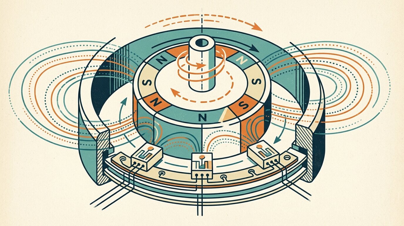
Bipolar-latching is built for rotation. Mount a ring of alternating N and S poles on a shaft, and the sensor's output flips state every time a pole boundary passes, holding each state until the opposite pole arrives - a natural fit for encoders for position feedback style speed and position counting, and for motor commutation, covered next.
Citation capsule: Unipolar Hall sensors respond only to one magnetic pole and ignore the opposite; omnipolar sensors respond identically to either pole, simplifying installation because magnet orientation no longer matters; bipolar-latching sensors require alternating poles - one turns the output on, the opposite turns it off - and hold that state until the field reverses (Texas Instruments; Honeywell, 2026). Bipolar latching is the pole behavior brushless motor commutation depends on.
How Do You Read the Sensitivity Specs - Gauss, Tesla, and mV/mT?
Magnetic field strength is given in gauss (G) or tesla (T): 1 tesla equals 10,000 gauss, so 1 millitesla equals 10 gauss. A linear sensor's sensitivity is its output change per unit of field, in mV/mT (Texas Instruments DRV5055, 2026). Get the units straight before comparing two datasheets, or the numbers mean nothing.
Sensitivity and range trade against each other directly. The Texas Instruments DRV5055 ships in variants at 100 mV/mT over a plus-or-minus 21 mT range, 50 mV/mT over plus-or-minus 42 mT, and 12.5 mV/mT over plus-or-minus 169 mT (Texas Instruments DRV5055, 2026). A 100 mV/mT part resolves small field changes precisely but saturates on a strong magnet or close mounting distance. A 12.5 mV/mT part covers a much wider field range at coarser resolution - pick it when the magnet sits close, runs strong, or the mounting tolerance is loose.
Digital switch thresholds live in this same unit system. A datasheet's Bop and Brp are usually specified in gauss or millitesla, so the same conversion applies whether you're sizing a linear sensor's range or checking whether a given magnet-to-sensor gap will reliably cross a switch's operate point.
Citation capsule: Field strength converts directly between units: 1 tesla equals 10,000 gauss, so 1 millitesla equals 10 gauss. Sensitivity and range trade off on linear Hall sensors - the Texas Instruments DRV5055 spans 100 mV/mT over +/-21 mT, 50 mV/mT over +/-42 mT, and 12.5 mV/mT over +/-169 mT (Texas Instruments DRV5055, 2026). Picking the wrong sensitivity for the expected field either saturates the output or throws away resolution you needed.
What Do Hall Sensors Actually Do?
Because they sense a magnet reliably and without contact, Hall sensors show up anywhere motion or current needs measuring: speed, position, commutation, and current. That range of jobs explains why the sensor is so common despite needing a magnet as a prerequisite (Honeywell; Allegro; MACCON, 2026).
Brushless DC motor commutation is the signature application. Three bipolar-latching Hall sensors, spaced around the rotor, each read a magnet mounted on the shaft and report which pole is passing. The motor controller uses that timing to fire the right coils in sequence; without it, a BLDC motor wouldn't know when to switch (Honeywell, 2026).
Gear-tooth and wheel-speed sensing pairs a back-biasing magnet with a Hall sensor facing a rotating ferrous target - an ABS tone ring, a gear, a toothed wheel. Each passing tooth disturbs the field enough to trip the sensor, and counting pulses per second gives RPM or wheel speed directly. Rotary and linear position sensing uses the same principle with a linear output instead of a switch, tracking a magnet's position continuously rather than counting pulses - a magnetic alternative to encoders for position feedback.
Non-contact current sensing reads the magnetic field a nearby conductor generates as current flows through it - exactly how a clamp meter measures current without breaking the circuit, galvanically isolated with no direct electrical connection to the sensed conductor. Flow meters use a smaller-scale version of the same trick, with a magnet embedded in a rotor and a Hall sensor counting rotations (Allegro; MACCON, 2026).

Citation capsule: Three bipolar-latching Hall sensors arranged around a brushless DC motor's rotor read a shaft-mounted magnet to tell the controller exactly when to switch coils - the mechanism BLDC commutation depends on entirely (Honeywell, 2026). The same magnet-plus-Hall-sensor principle also drives gear-tooth speed sensing for ABS and RPM, rotary and linear position feedback, non-contact current sensing, and flow-meter rotor counting.
Hall vs Inductive Proximity - When Should You Use Each?
Both are non-contact, but they sense different physical things. A Hall sensor detects a magnetic field, so it needs a magnet or a magnetized target, and it sees straight through non-ferrous barriers. An inductive sensor detects any metal target by eddy currents at close range, no magnet required (MACCON, 2026).
That single distinction - what triggers the sensor - decides the choice before range, cost, or mounting enter the conversation. If your job is magnet-based (position, speed, commutation, current) or the target sits behind a non-magnetic wall, Hall wins outright; inductive sensors can't see through a barrier the way a magnetic field can. If the job is detecting any metal part at close range on a busy production line, inductive is the simpler, cheaper answer, and it skips gluing a magnet to anything.
Choose Hall when:
- The target already is, or can be fitted with, a permanent magnet
- You need to sense through a non-ferrous wall or sealed enclosure
- The job is motor commutation, shaft speed, or current sensing
- Cost matters at scale - a basic Hall IC runs roughly $1 (MACCON, 2026)
Choose inductive when:
- The target is bare metal with no magnet fitted or feasible
- You need to detect any metal part regardless of composition
- The environment is dirty or wet and eddy-current immunity to non-conductive contamination matters more than through-wall reach - see inductive vs capacitive proximity sensors for that comparison in full
| Attribute | Hall-effect | Inductive |
|---|---|---|
| Senses | A magnetic field | Any metal, via eddy currents |
| Needs a magnet | Yes - or a magnetized/back-biased target | No |
| Through non-ferrous walls | Yes | No |
| Typical use | Magnet-based position, speed, commutation, current | Detecting any metal part at close range |
| Environment robustness | Good; solid-state | Very robust to dirt and heat |
| Relative cost | Low, roughly $1 | Higher |
| Best for | Motor commutation, speed, current, sensing through plastic or aluminum | Rugged close-range metal detection in harsh conditions |
Hall wins when a magnet is already there or the target sits behind a non-ferrous wall; inductive wins for bare metal detection in harsh, close-range conditions. For light-based sensing, explore photoelectric sensor types.
Citation capsule: A Hall-effect sensor detects a magnetic field and therefore requires a magnet or magnetized target, but can sense through non-ferrous barriers that would block other technologies entirely. An inductive proximity sensor detects any electrically conductive metal target via eddy currents at close range, with no magnet needed, and a basic Hall IC costs roughly a dollar at volume (MACCON, 2026). The choice comes down to whether the application already has, or can add, a magnet.
How Do Temperature and Drift Affect Reliability?
Hall sensors are solid-state and rugged, but both the sensor chip and its magnet drift with temperature, so industrial-grade parts compensate for it. Neodymium magnets lose roughly 0.12% of their field strength per degree Celsius; ferrite magnets lose about 0.20% per degree Celsius (Texas Instruments; Allegro, 2026).
Modern Hall ICs counter that drift with sensitivity temperature compensation - deliberately increasing the sensor's own sensitivity as temperature rises to offset the magnet's weakening field - plus chopper stabilization, which cancels offset drift in the amplifier stage itself (Texas Instruments, 2026). A well-designed sensor-plus-magnet system holds its calibration far better than either component would alone.
Operating temperature ranges typically span -40 to 85 degrees Celsius for standard parts, up to 125 or 150 degrees Celsius for automotive and industrial grades - but even those high-temp parts see measurement performance degrade above roughly 120 degrees Celsius (Texas Instruments; Honeywell, 2026). Mounting matters too: stray fields from nearby motors, cables, or ferrous fixtures can shift a switch's effective threshold, so datasheet Bop/Brp specs assume a clean field with no external interference.
Citation capsule: Permanent magnets weaken with heat - neodymium drifts roughly -0.12% per degree Celsius, ferrite roughly -0.20% per degree Celsius - which modern Hall ICs offset with built-in sensitivity temperature compensation and chopper stabilization (Texas Instruments; Allegro, 2026). Standard parts operate from -40 to 85 degrees Celsius, with automotive and industrial variants rated to 125 or 150 degrees Celsius, though measurement accuracy degrades above roughly 120 degrees Celsius even on the higher-rated parts (Texas Instruments; Honeywell, 2026).
Frequently Asked Questions
How does a Hall-effect sensor work?
A magnetic field passing through a current-carrying semiconductor pushes the moving charges sideways, creating a small voltage across the chip proportional to the field strength - an effect Edwin Hall discovered in 1879 (Texas Instruments, 2026).
What is a Hall-effect sensor used for?
Hall sensors handle motor commutation, gear-tooth speed sensing for ABS and RPM, rotary and linear position, and non-contact current sensing, because they read a magnet reliably without touching anything (Honeywell; Allegro, 2026).
What are the types of Hall-effect sensors?
Two axes cover almost every part: output style (digital switch or linear/ratiometric) and pole behavior (unipolar, bipolar-latch, or omnipolar). Combine an output style with a pole type and you have described the sensor (Texas Instruments, 2026).
What is the difference between a digital and a linear Hall sensor?
A digital Hall sensor gives a clean ON/OFF output that flips at a magnetic threshold, with hysteresis to stop chatter. A linear sensor gives a continuous voltage proportional to field strength, sitting at Vcc/2 with no field (Texas Instruments DRV5055, 2026).
Hall sensor vs inductive proximity - which should I use?
Choose Hall when you need to sense a magnet through a non-ferrous wall, measure current, or commutate a motor. Choose inductive when you need to detect any metal target at close range in a dirty or harsh environment (MACCON, 2026).
Conclusion
A Hall-effect sensor turns a magnetic field into a voltage - a small effect Edwin Hall found in 1879, now packaged into a solid-state chip with no moving parts. Two choices decide what it does: digital (a switch with Bop/Brp hysteresis) versus linear (ratiometric, sensitivity in mV/mT), plus unipolar, omnipolar, or bipolar-latch pole behavior for rotation and commutation.
Because it senses a magnet rather than any metal, it beats inductive sensing for magnet-based speed, position, and current work, and it reads straight through non-ferrous walls where inductive can't follow. Watch temperature drift on both the sensor and the magnet, and pick the sensitivity range that matches your expected field.
For the wider detection-technology picture, read the industrial sensors guide. For the eddy-current alternative covered in full, see inductive vs capacitive proximity sensors.
How does a Hall-effect sensor work?
A magnetic field passing through a current-carrying semiconductor pushes the moving charges sideways, creating a small voltage across the chip proportional to the field strength - an effect Edwin Hall discovered in 1879 (Texas Instruments, 2026).
What is a Hall-effect sensor used for?
Hall sensors handle motor commutation, gear-tooth speed sensing for ABS and RPM, rotary and linear position, and non-contact current sensing, because they read a magnet reliably without touching anything (Honeywell; Allegro, 2026).
What are the types of Hall-effect sensors?
Two axes cover almost every part: output style (digital switch or linear/ratiometric) and pole behavior (unipolar, bipolar-latch, or omnipolar). Combine an output style with a pole type and you have described the sensor (Texas Instruments, 2026).
What is the difference between a digital and a linear Hall sensor?
A digital Hall sensor gives a clean ON/OFF output that flips at a magnetic threshold, with hysteresis to stop chatter. A linear sensor gives a continuous voltage proportional to field strength, sitting at Vcc/2 with no field (Texas Instruments DRV5055, 2026).
Hall sensor vs inductive proximity - which should I use?
Choose Hall when you need to sense a magnet through a non-ferrous wall, measure current, or commutate a motor. Choose inductive when you need to detect any metal target at close range in a dirty or harsh environment (MACCON, 2026).
Related Articles

